







What an ATS is and when you can't do without one
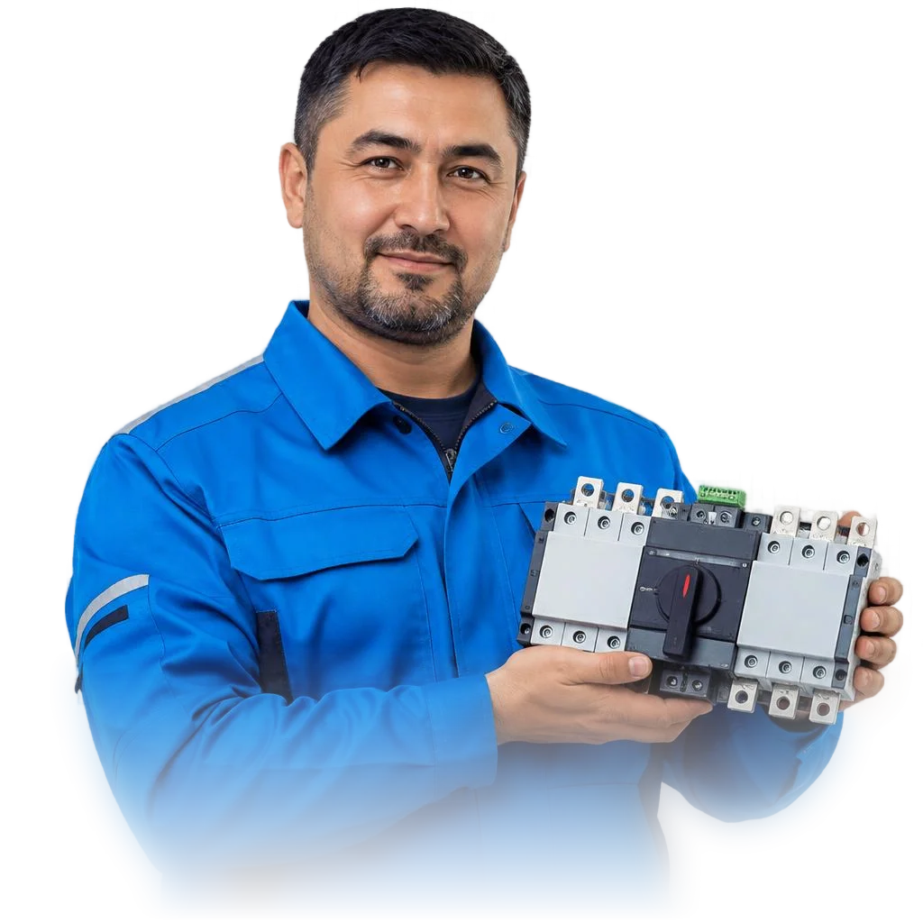
An automatic transfer switch is not a "breaker in a panel" but a system of several coordinated devices that keeps a site powered when the grid fails. Below we'll look at what it consists of, how it differs from a manual switch, and who needs one.
What an ATS is and what the system consists of
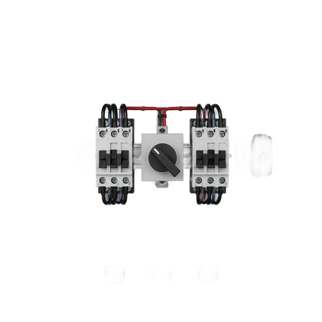
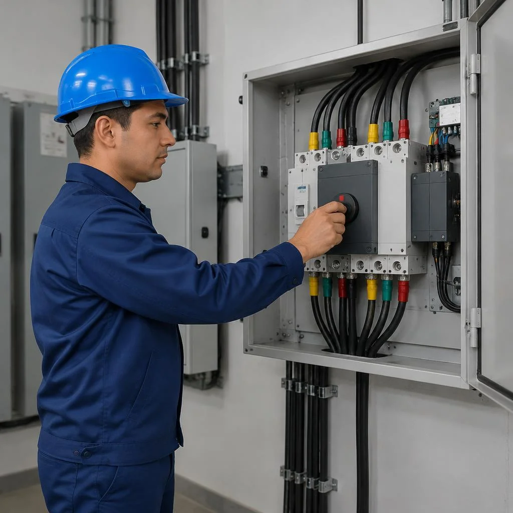
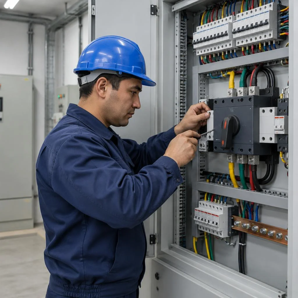
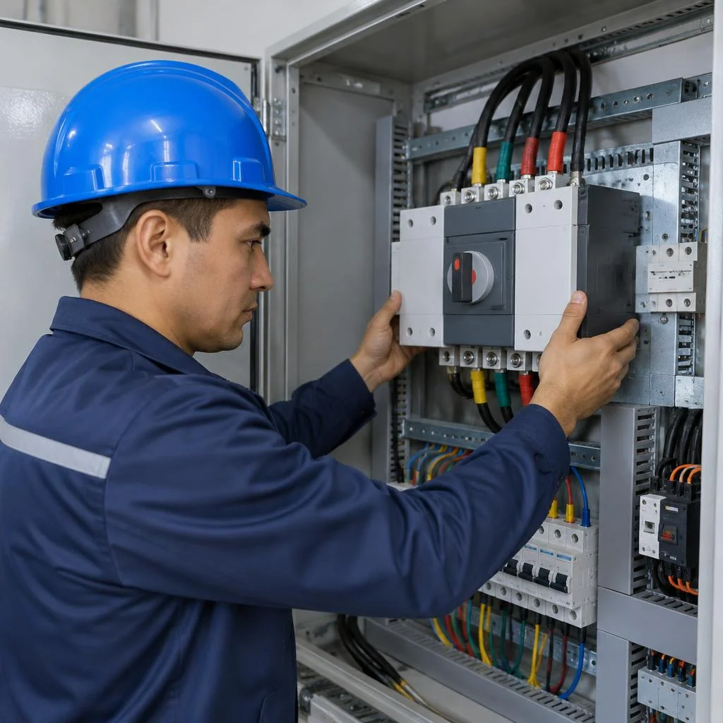
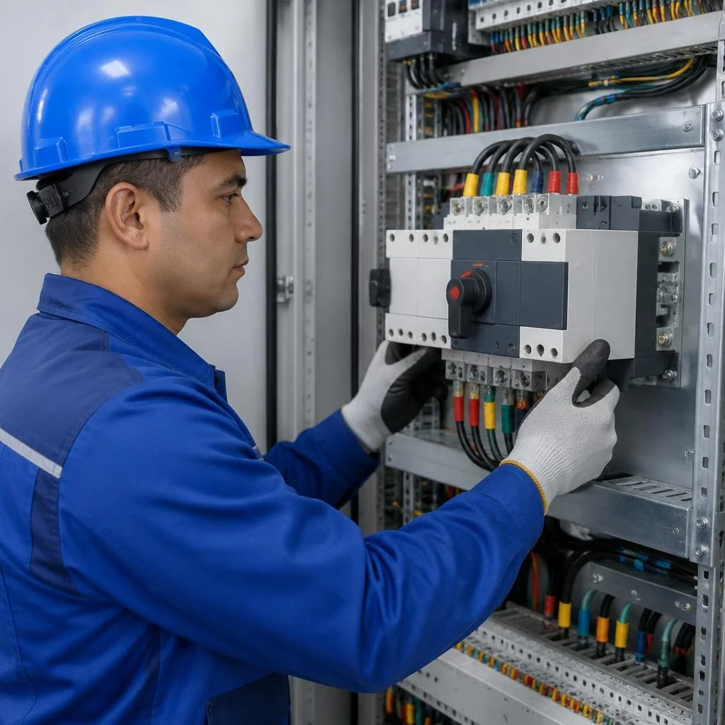
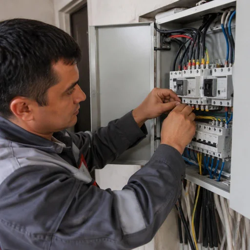
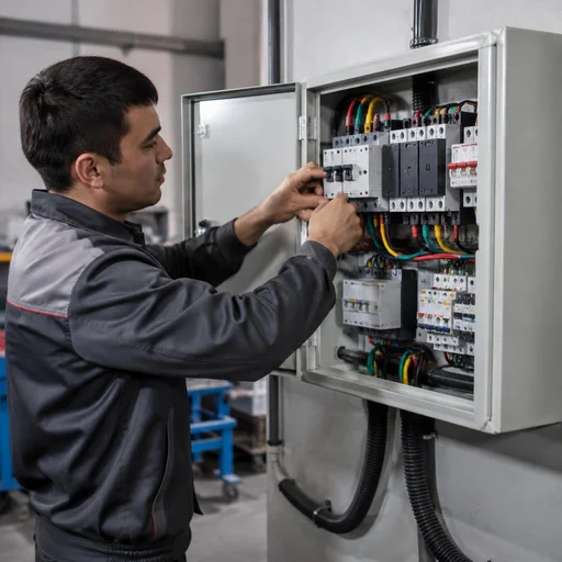
An ATS (automatic transfer switch) is an assembly consisting of an incoming circuit breaker, a contactor, a voltage monitoring relay and a priority relay, which in seconds switches a site's power from the main line to the backup one. The incoming circuit breaker protects the line from overload and short circuit, the contactor physically closes and opens the power circuits, the voltage monitoring relay monitors the level on the main line, and the priority relay decides which input is considered the working one at any given moment. Terminal blocks and installation wire inside the panel tie it all together: they carry the signal from the relay to the contactor coil. The tripping sequence is simple — the main line, the voltage monitoring relay, switching to backup. A contactor alone without a priority relay does not provide correct switching: when the main line returns, the power may "jitter" between inputs, so the logic is always assembled as a complete set.
How an ATS differs from a manual switch
A manual switch requires a person to physically act, whereas an ATS trips on its own — the typical switching time is a fraction of a second, while manual switching takes from several minutes. The difference is critical not in calm mode but at the moment of an accident: while the operator is looking for the panel and turning the handle, the site is already de-energized. Automatic switching happens on a signal from the voltage monitoring relay, and the backup input picks up the load without human involvement. During brief grid "flickers" a manual switch is useless — a person physically cannot react in time, and the equipment (refrigerators, servers, machine tools) has already taken a surge. Installing an automatic transfer switch covers exactly this scenario: the automation responds faster than any operator's reaction.
Who needs an ATS: house, apartment, office, shop, production
- Private house: an overhead line causes frequent outages, and the automation picks up the load without manually starting a generator.
- Apartment: a single-phase scheme with a voltage monitoring relay is enough; a three-phase assembly here makes the project more expensive with no benefit.
- Office: switching to backup preserves servers, cash registers and workstations during a failure on the city grid.
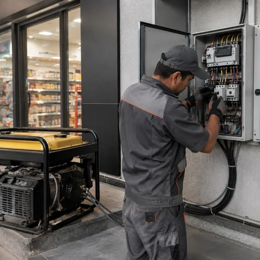
- Shop: pairing with a generator keeps refrigerated display cases and the checkout unit running; downtime directly hits revenue.
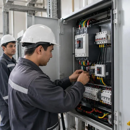
- Production: a three-phase ATS with input priority keeps machine tools from stopping and protects equipment from a phase-loss condition.
- Eco-Service: installs automation at all five types of sites, selecting the scheme and capacity for each.
How ATS works and how to select a scheme for the load
We break down the logic of automatic transfer switching and how load power determines the choice of a single-phase or three-phase scheme, priority, and protections.
Logic of automatic transfer switching
A voltage monitoring relay keeps an eye on the main line; when parameters go beyond acceptable limits, it sends a command to the contactor, and the load is transferred to the backup input, and when restored — it switches back. In a typical scheme, the relay monitors the 170–265 V range on each phase: going beyond the limits for longer than 0.5–1 second triggers switching, and a 40–63 A contactor breaks the main circuit and closes the backup one within 0.3–0.8 seconds. There is a delay between commands: return to the main line does not happen immediately, but 5–180 seconds after voltage stabilization. Installing automation at facilities with an unstable grid is exactly the task where the return delay matters more than the contactor's power: it protects against chatter when voltage jumps several times in a row, and with frequent switching, the resource of a contactor rated for 100,000 cycles is used up in just a few months.
Single-phase or three-phase ATS: how to choose
| ATS type | For which facilities | Load nature | What it protects |
|---|---|---|---|
| Single-phase | Apartments, houses up to 7 kW | Lighting, sockets, household appliances | One phase and neutral |
| Three-phase | Cottages, shops, offices, workshops | Motors, pumps, furnaces | All three phases and neutral |
| Hybrid | Facilities with mixed input | Single-phase and three-phase part | Each group separately |
We select a single-phase ATS for apartments and small houses with a load of up to 7 kW, and a three-phase one for facilities with a three-phase input: cottages, shops, offices, and production sites. Power is calculated based on the total current of all consumers with a 20–30% margin: for a 15 kW house, this is a 25 A input circuit breaker, for a workshop with motors — 63 A and above.
Setting input priority and protection selectivity
We set the input priority so that the main line is always primary, and the backup is switched on only when it fails — this eliminates false switching. The priority relay operates on the "main input first" logic: as long as the voltage on it is normal, the backup contactor is held open, even if the generator is already running and ready for load. Protection selectivity is selected by ratings: the input circuit breaker is set one step higher than the group ones, so that in the event of a short circuit on the line, the group breaker trips, not the entire facility. At facilities with two inputs from different feeders, priority is fixed on a permanent basis — switching occurs only on command from the voltage monitoring relay. If the input circuit breaker and the group breaker have the same current rating, in the event of an accident the entire facility will be disconnected, not just the individual line, so the ratings are separated by at least one step — for example, 25 A at the input versus 16 A on the groups.
ATS installation: stages of work and what the service includes
We will show the sequence of work — from cable laying to commissioning, so it is clear what the installation consists of and what is checked at each stage.
Preparation: cable laying and installation of the input circuit breaker
- Cross-section calculation: the input cable is selected for the rated current of the input circuit breaker, not "by eye" — an undersized cross-section heats up under load and negates the protection.
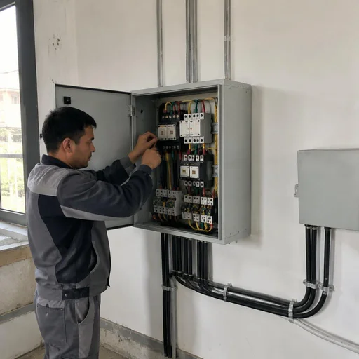
- Laying to the ATS panel: the route is run from the entry point to the installation location, walls are chased or the cable is laid in corrugated conduit and cable tray.
- Installation of the input circuit breaker: the device is installed first in the circuit so that it disconnects both the main and backup line in the event of an overload.
- Marking: each conductor is labeled by phase and purpose — during servicing this saves hours of diagnostics.
- Check before energizing: before the first start, the line is continuity-tested and the ratings are verified against the design — this way work whose cost is calculated after inspecting the site does not turn into rework.
Connecting the ATS to the input cable and backup supply
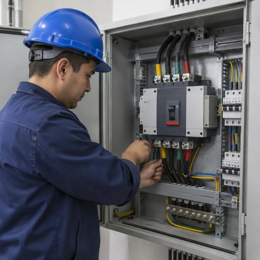
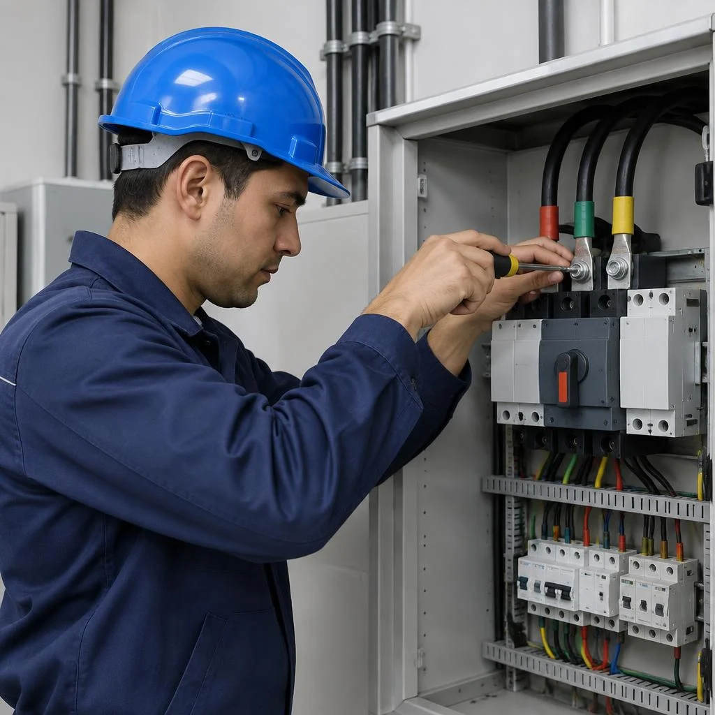
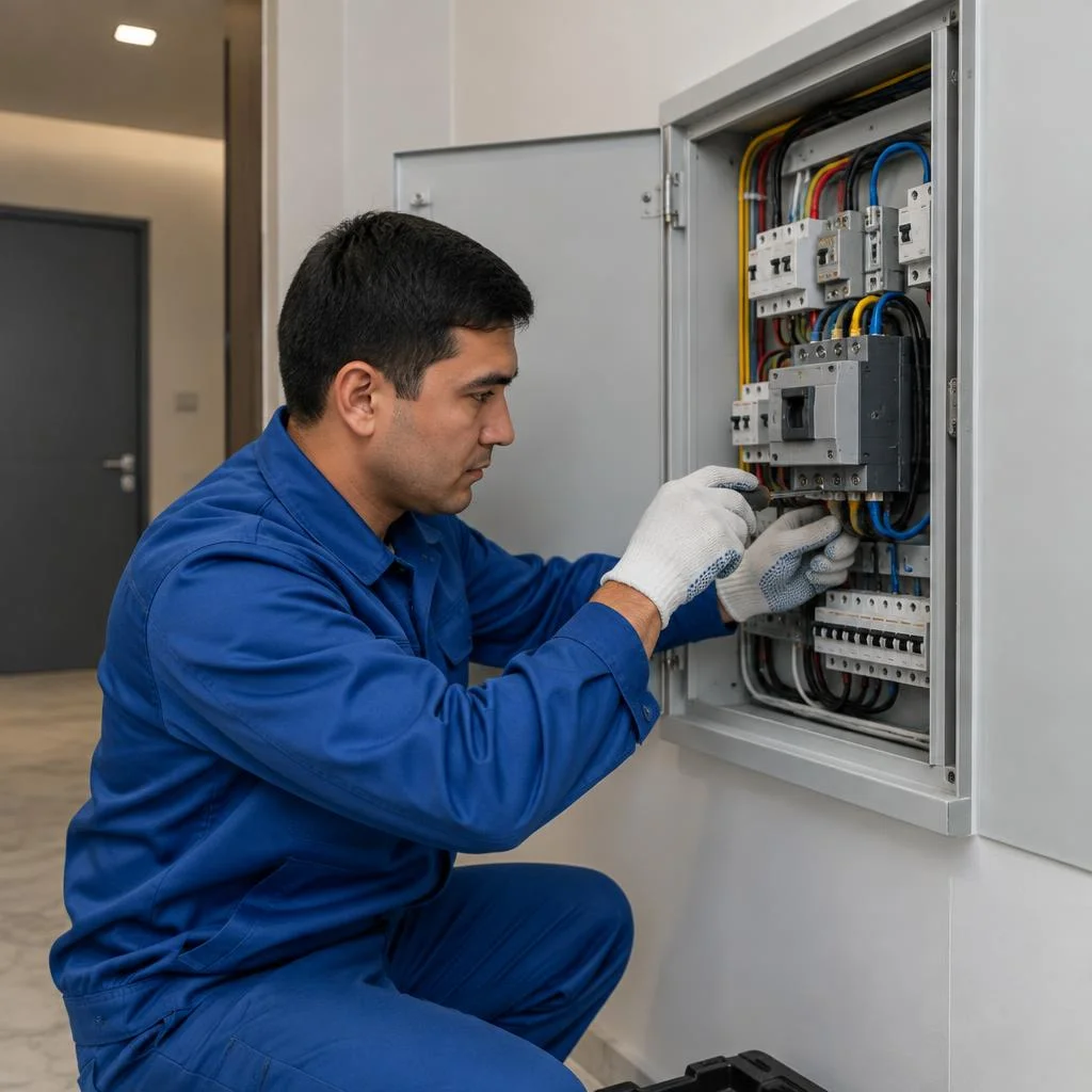
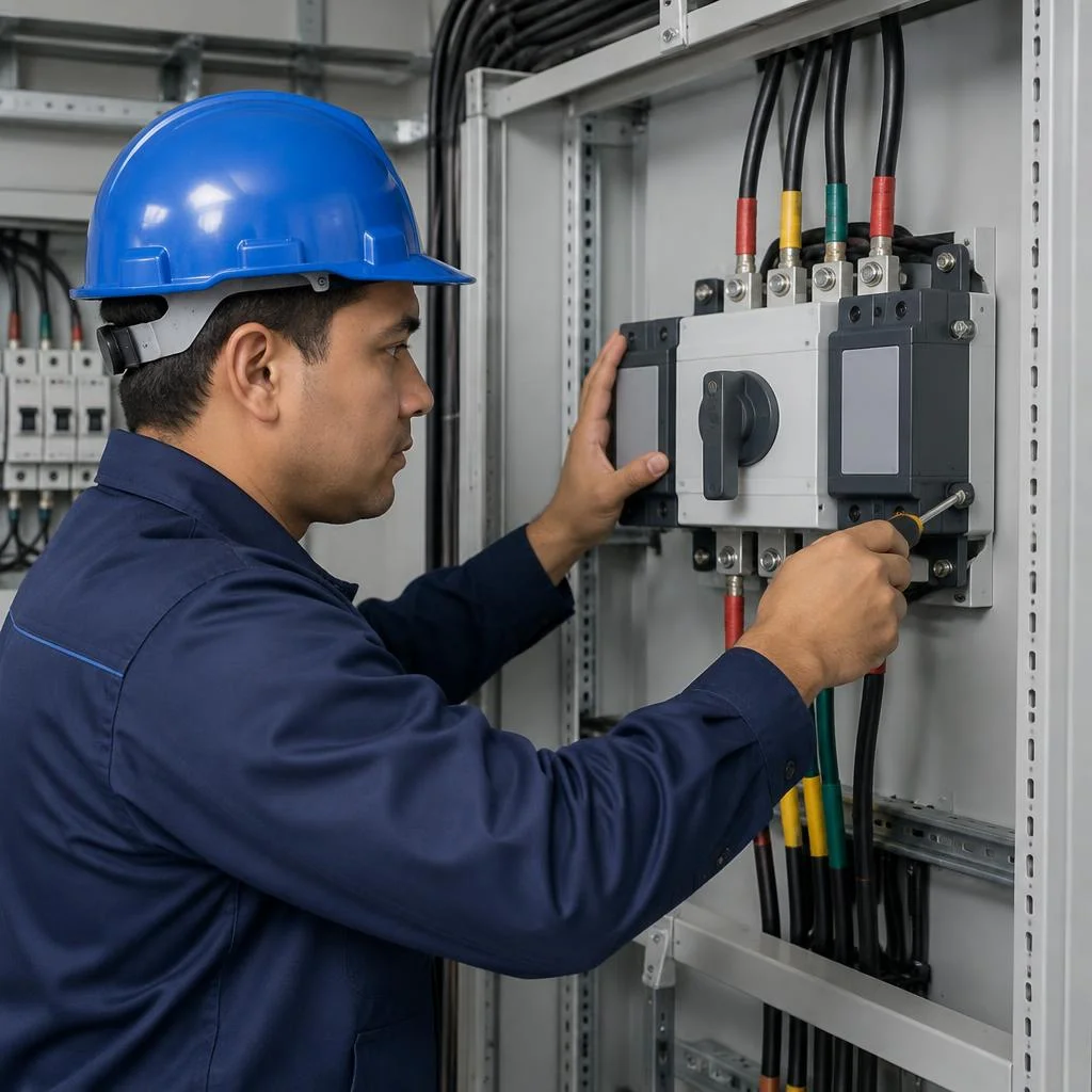
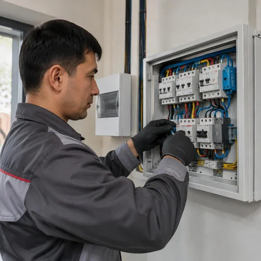
Eco-Service connects the ATS to the input cable and configures it for the backup supply — after that the unit is ready for automatic switching. The terminals of the main line and the backup are tightened to the torque specified in the device's datasheet: a loose contact under load heats up within minutes of operation. The phase sequence of both supplies is checked with a phase rotation indicator — if the phase rotation order differs, a three-phase motor of a pump or machine will go into reverse when switched and fail. On the backup supply, the setpoints are additionally configured and the mechanics of the changeover contactor are tested manually, before energizing. If the main and backup lines are phased differently, the connection order at the terminals is changed, rather than "treating" the consequences on the consumer side.
ATS commissioning after installation
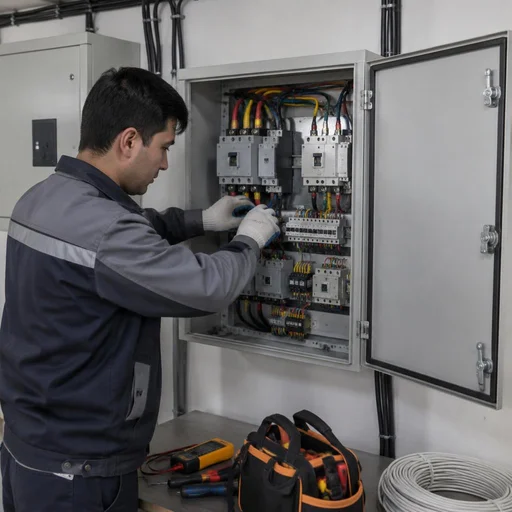
Eco-Service completes the installation with commissioning: it simulates a loss of the main line and checks that the ATS correctly switches the load to the backup and returns it back. First, power is removed from the main line and the response time is recorded — for household models this is a matter of seconds, for industrial ones with a return delay the parameter is configured separately. Then, under the actual load of the site, it is checked how the contactor handles the starting current of a pump, compressor or machine: at no load the unit works flawlessly, but under peak load both a weak contact and an incorrect setpoint become apparent. The return to the main line is also tested — with a delay, so that the generator does not "jitter" during short dips in the grid. Clients often search for ATS installation price — and land on this page, although the final estimate is formed only after inspecting the site and checking the input cable. Commissioning is carried out under the actual load of the site, not "at no load" — only this way can you see whether the contactor will withstand the starting current of a pump or machine.
Assembling a panel with ATS: layout and overload protection
The panel is where all the input switching logic comes together: commutation, priority, load protection. Let's break down what a well-designed layout consists of, which protective elements are installed alongside, and how to choose an enclosure for the conditions at the site.
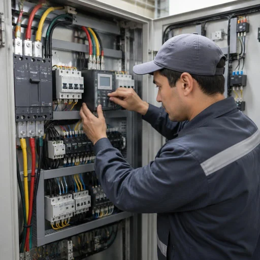
What is included in assembling a panel with ATS
- Main circuit breaker: protects the supply line from overcurrent and serves as the disconnection point for the entire panel during maintenance.
- Input contactors: mechanically switch the load between the main and backup inputs based on a signal from the priority relay.
- Voltage monitoring relay: monitors the grid parameters and issues a command to switch when there is a voltage sag or surge.
- Priority relay: determines which input is considered the main one and which is only switched on when it fails.
- Terminal blocks and busbars: combine neutral and grounding conductors, simplifying the connection of outgoing lines.
- Line marking: labels and a diagram on the panel door that the technician uses for orientation during repairs.
Overload protection and voltage monitoring relay
Assembling a panel with ATS at Eco-Service is done as a complete set, not as a collection of separate modules: the work here finishes with marking each line and a diagram on the door. Marking is not a formality: during future repairs or relocation, a technician without a diagram spends hours on continuity testing instead of quickly replacing a module. Installing automation at sites with gas boilers and pumps requires narrowed thresholds — the electronics of control boards are sensitive to deviations, while for power equipment a standard corridor is left. At sites with frequent fluctuations, relays are installed on both inputs, not just the main one: the backup line from the generator also produces unstable parameters at startup. Overload protection is configured according to the rating of the main circuit breaker and the cable cross-section, while the voltage monitoring relay trips on sags below normal and on surges above the operating range.
Panel enclosure IP protection rating
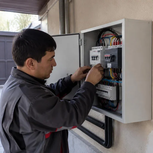
For a panel with ATS indoors, an enclosure with an IP31–IP41 protection rating is sufficient, while for outdoors or an unheated room, IP54 and higher is needed. In a dry heated vestibule or electrical room, IP31 is enough: the enclosure protects against solid particles and vertical drips. In a garage, on a veranda, or under a canopy where moisture and dust are possible, IP54 is used with a sealed door and cable glands for the cable. In rooms with high humidity — a sauna, boiler room, laundry — IP65 and higher is installed, sometimes with enclosure heating in winter. Moisture and dust are the main enemies of a contactor: in a damp room, oxidized contacts stick, and the ATS stops switching precisely at the moment of an emergency. If the site is near open ground or outdoors, allow for an enclosure with an IP margin — the difference in panel cost is incomparable to the cost of replacing a burnt-out contactor and downtime without power.
Connecting the ATS to a generator and working with a backup source
A backup generator is the most common power source on the second input after the city grid. Let's break down how the automation links it to the panel, what auto-start changes, and which mistakes most often lead to unit failure.
How the ATS links to the generator
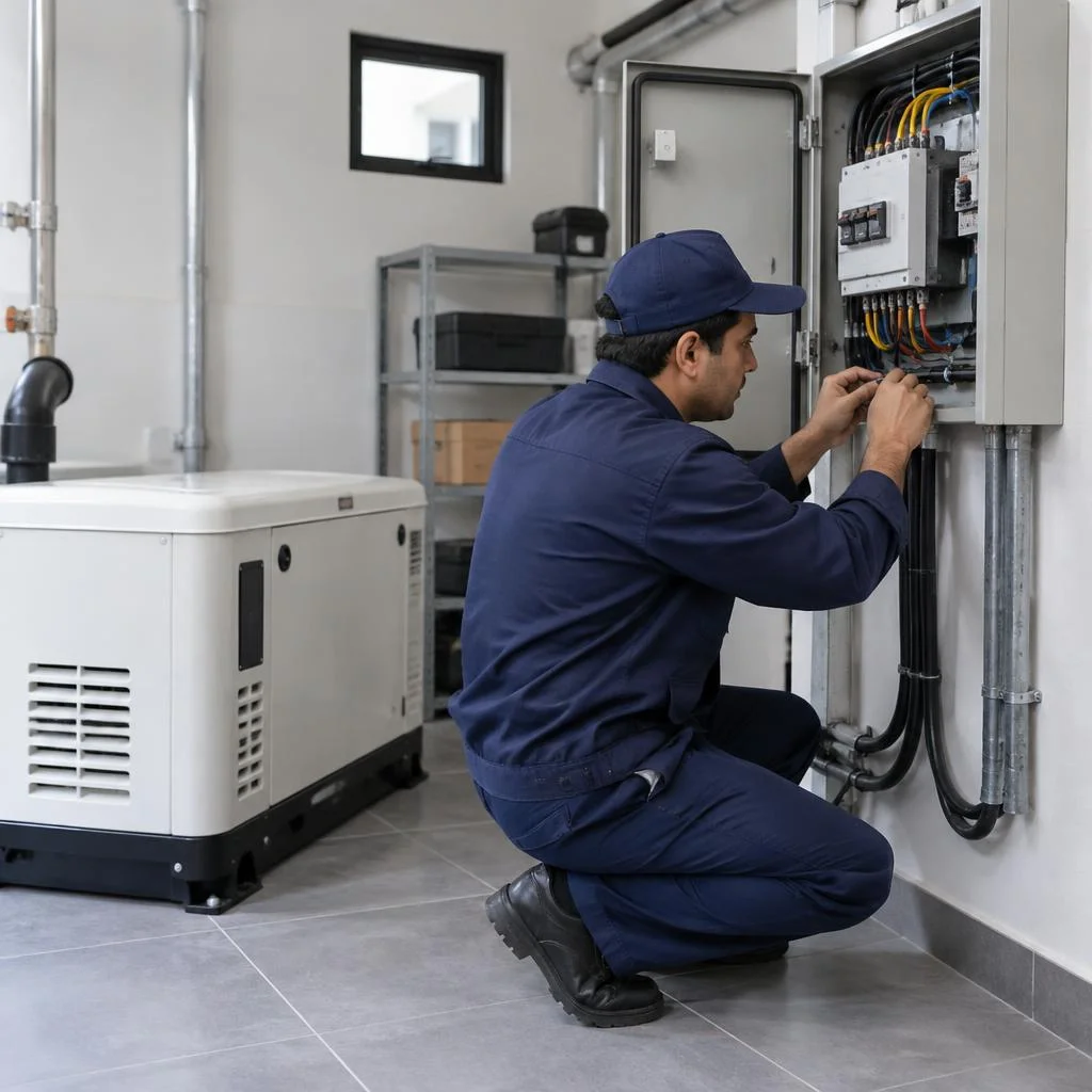
Eco-Service connects the ATS to the generator in such a way that when the main grid is lost, the unit sends a signal to start the generator and only after it reaches operating mode does it transfer the load to the backup. Installing automation at a site with a generator requires a separate control line between the panel and the generator: the start command travels along it, and the readiness status is returned via a contactor. The start automation holds a warm-up pause — usually from 5 to 15 seconds, until the engine reaches rated speed, and during all this time the backup input contactor remains open. This sequence is the basis of any installation at a site with a generator. The load cannot be transferred to the generator immediately after startup — in the first seconds the voltage and frequency are unstable, and the equipment gets the same surge that the ATS is designed to protect against.
ATS with auto-start: what it gives the site
- Auto-start setup: at Eco-Service, the ATS controller is linked to the generator automation, setting the voltage trip threshold and the pause time before start.
- Load test: we simulate a grid loss, measure the time from the command to the load transfer, and check that the generator holds its rated output without sagging.
- Maintenance schedule: we set the frequency for checking the battery, fuel level, and automation contacts so that the unit doesn't fail at the critical moment.
- Unattended backup: the site switches to generator power automatically, which is critical for stores, offices, and production facilities with a continuous cycle.
Typical mistakes when connecting a generator to an ATS
- Counter-switching: the generator remains running after the grid returns, the two lines converge at one point, and the protection trips.
- Undersized capacity: the backup generator doesn't cover the starting current of a pump or machine, the voltage sags, and the automation enters a switching cycle.
- Missing neutral: the generator is connected without a solidly grounded neutral, the voltage monitoring relay sees an imbalance, and blocks the transfer.
- Single control circuit: the start command travels along the power line instead of a separate wire, causing the automation to pick up interference and trigger falsely.
- No warm-up pause: the load is transferred immediately after the engine starts, and the equipment gets a surge in frequency and voltage.
Warranty, timelines and service: how Eco-Service manages a project
Let's break down what the warranty covers, how long installation takes and what service looks like after the project is handed over — from scheduled inspection of contactors to replacement or relocation of the unit to a new location.
Warranty on ATS installation — 2 years
Eco-Service provides a 2-year warranty on ATS installation — it covers work on connection to the incoming cable, panel assembly and commissioning. During this period, defects caused by our fault are rectified free of charge: loosened terminal connections, incorrect setting of the input priority, faults in the logic of switching to the backup input. The warranty is valid subject to compliance with the operating regulations: if the owner re-wires the panel themselves or connects additional load beyond the calculated one, warranty obligations for that unit are voided. In my experience, it's more often not the automation that fails, but specifically the connections — re-tightening them after the first month of operation is part of the service. Before signing the acceptance certificate, ask to be shown the terminal tightening torque on the input and on the contactor: this parameter is rarely documented, yet it determines the service life of the unit.
How long ATS installation takes
Eco-Service completes ATS installation in an apartment or private house within one working day, while on projects with a three-phase input and panel assembly the work takes up to two days. A full cycle fits into a standard day: laying the cable to the panel, installing the input circuit breaker, connecting to the backup input and commissioning with testing of switching under load. The timeline depends not on the unit itself, but on the preparation: if the cable to the panel is not laid and the input circuit breaker is not installed, a preparatory stage is added to the installation — on Tashkent projects this means plus one day. When a client asks about ATS installation price, I always clarify the scope of supply: preparation, panel assembly and automation setup are counted as separate items, so the total depends on what has already been done on the project.
Maintenance and replacement of the ATS after project handover
- Scheduled inspection: once a year we inspect contactors, voltage monitoring relays and terminal connections for overheating and scorching.
- Re-tightening connections: we tighten the terminals on the input and on the contactor — a loosened contact heats up and accelerates wear of the unit.
- Switching test: we simulate a power failure and check that the automation switches to backup within the calculated time.
- ATS replacement: if the unit fails, we replace it with a new one using the same connection diagram and repeat commissioning.
- Relocation to a new location: when the input changes, we dismantle the unit, re-lay the cable and configure the priority.
Conclusion
We have gathered the key takeaways on ATS installation: from choosing the scheme to connecting the generator and maintenance. Below is what determines the stable operation of backup power on a project.
Main takeaways
- An ATS is a system: correct operation depends on the set of devices — input circuit breaker, monitoring relay, contactors and panel — and not on a single switch.
- Scheme matched to the load: the choice of single-phase or three-phase configuration is determined by the type of input and the nature of the consumers — from lighting to machine tools.
- Full installation cycle: preparation, connection to the incoming cable, panel assembly and commissioning under real load — without the last stage the system is not tuned.
- Backup source: pairing with a generator requires setting up auto-start, checking phase rotation and coordinating the priority of inputs.
- Warranty and service: a two-year warranty and regular maintenance extend the service life of the unit and protect equipment on the project from surges and voltage drops.