










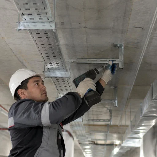
What a cable tray is and what tasks it solves at a facility
A cable tray is a load-bearing metal structure for open cable routing. In commercial, industrial and warehouse buildings in Tashkent, no extended route can do without it.
What a cable tray is and how it differs from a cable duct
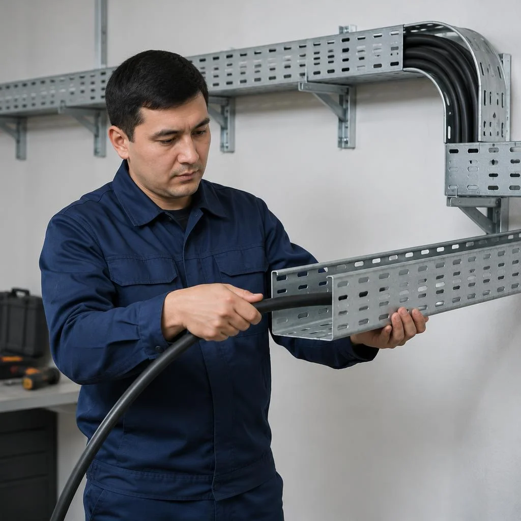
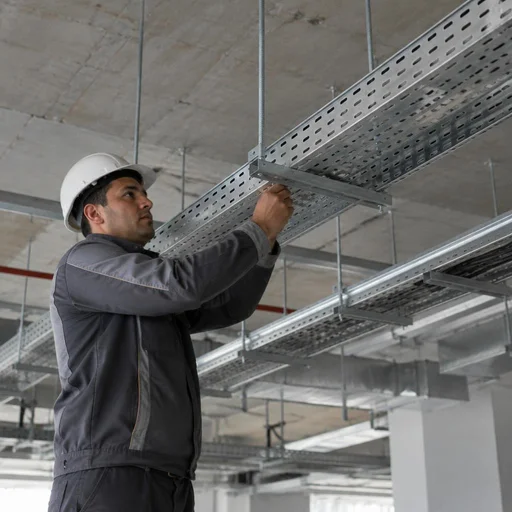
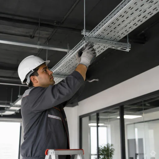
A cable tray is an open load-bearing metal structure along which cable is laid without being pulled into a conduit, which simplifies installation and maintenance. A cable duct is a closed box made of plastic or thin steel with ready-made compartments for 2-4 lines, designed for low-voltage systems and power groups of small cross-section. A tray is assembled from perforated, wire mesh, ladder or solid sections with a width of 50 to 600 mm and carries a bundle of 15-40 cables at once. It is fastened to brackets, cantilevers and ceiling hangers at a spacing calculated based on the weight of the route. Cable tray installation is how clients most often phrase the task when they need an open route for a bundle of lines. Unlike a cable duct, a tray is designed for a bundle of cables with a total load of up to tens of kilograms per meter — which is why it is used where a duct physically cannot withstand the load. If the design specifies more than eight power lines in one direction, calculate a tray route rather than a duct — otherwise the fasteners will have to be redone on site.
Where tray routes are used at facilities in Tashkent
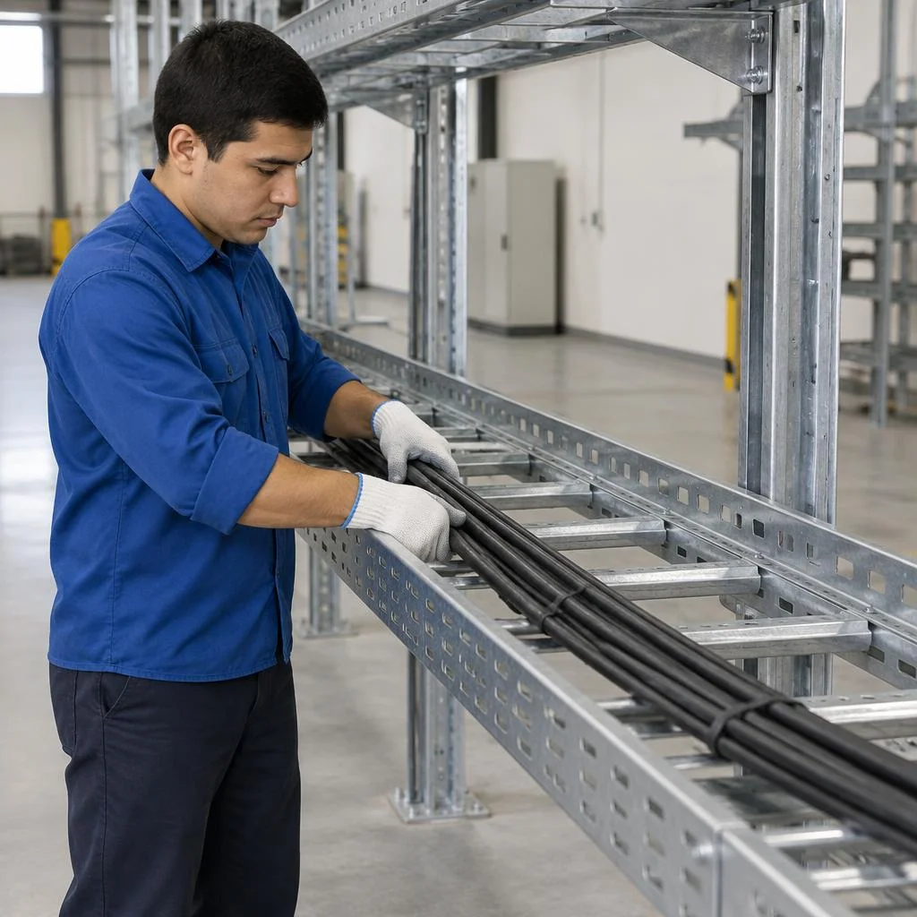
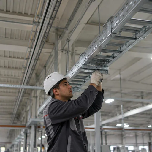
- Warehouses and logistics hubs: the route runs along the ceiling parallel to the racking lines — the lower tier remains free for storage and forklift traffic.
- Business centers and offices: the tray runs above the suspended ceiling and in technical corridors, from where lines are routed to distribution boards and floor risers.
- Sales floors and supermarkets: open wire mesh trays are installed under the ceiling tiles — they do not block light fixtures or ventilation grilles.
- Production workshops: ladder trays carry power feeders to machine tools and crane equipment, where vibration resistance is important.
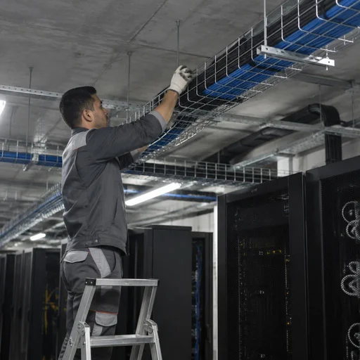
- Server rooms and communication nodes: a perforated tray separates power and low-voltage lines and provides access to an individual branch without disassembling the route.
What a tray route consists of: elements and components
- Tray sections: straight lengths of 2 or 3 meters — perforated, wire mesh, ladder or solid.
- Brackets: wall-mounted supports that hold the tray on a wall or column and set the projection from the base.
- Cantilever supports: reinforced brackets for wide trays and heavy cable bundles.
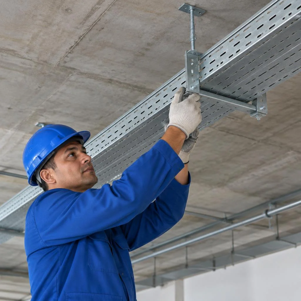
- Crossbars: transverse beams on which the tray rests when fastened to ceiling hangers.
- Section connectors: plates and bolt kits that join adjacent lengths into a continuous line.
- Corner elements and tees: ready-made 90, 45 and 135 degree angles and branches for routing the route in several directions.
- Reducers and end caps: parts for changing the tray width and neatly closing the open ends of the route.
Types of cable trays we install: from wire mesh to stainless steel
On sites, we install five types of tray systems — wire mesh, perforated, metal, ladder and stainless steel. The choice is dictated by three things: the total load of the route, the aggressiveness of the environment and the installation budget.
Comparison of tray types by load and application environment
| Tray type | Load | Application environment | Installation feature |
|---|---|---|---|
| Metal | medium and high | universal | mounted on brackets |
| Perforated | medium | ventilated rooms | perforation for ties and clamps |
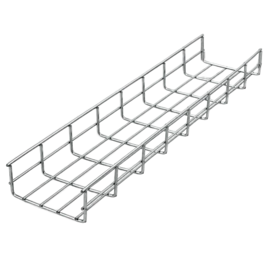
| Wire mesh | low | offices, low-voltage systems | lightweight, quick assembly |
| Ladder | high | power routes, workshops | rungs for heavy cable |
| Stainless steel | medium and high | damp and aggressive environments | resistant to corrosion |
We select the tray type based on three parameters: the total load per metre, the aggressiveness of the environment and the cable ventilation requirements. Eco-Service installs all five varieties, and on a single industrial site a ladder tray in the workshop and a wire mesh tray in the administrative wing often sit side by side. For low-voltage systems at office sites, a wire mesh tray is more advantageous than a perforated one in terms of weight — ceiling suspensions require fewer attachment points.
Metal and perforated trays: when to use which
We install perforated trays where the cable needs to be frequently secured with ties or where ventilation is important, and smooth metal trays on long straight sections without intermediate fastenings. In office centres, perforation helps secure twisted pair every 30-40 centimetres, while in warehouses a smooth metal tray holds power cable without unnecessary holes in the body. Perforation reduces the section's torsional rigidity — at route turns, a perforated tray requires an additional bracket closer to the corner. When installing metal and perforated trays, Eco-Service specifies fasteners for the specific load, so when choosing a tray type, first check the cable weight per metre, and only then look at the price of the section.
Wire mesh and ladder trays: light and heavy routes
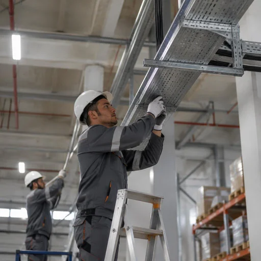
We use wire mesh trays for low-voltage lines and short branches, and ladder trays for power routes with heavy large-cross-section cable. In business centres, wire mesh systems save up to a third of the weight of the suspended structure, while in workshops a ladder tray holds cable with a cross-section of 120-240 mm² over spans between supports. The ladder tray is convenient because the cable can be laid with spacing between the rungs — this simplifies pulling long sections without intermediate pull boxes. When cable tray installation is ordered, the price is calculated by the type of route: light wire mesh sections cost less in fasteners than ladder sections with reinforced cantilevers. Laying cable trays along ceiling slabs goes faster if the wire mesh sections are pre-assembled into 3-4 metre blocks on the floor, rather than being lifted up one at a time.
Stainless steel tray for aggressive environments
We install stainless steel trays in rooms with humidity, chemical environments or in food production facilities, where galvanised coating corrodes quickly. In food industry enterprises and washing rooms, AISI 304 stainless steel lasts for decades, whereas zinc coating loses its protective properties within 3-5 years under constant humidity. Stainless steel is more expensive to install not because of the material, but because of the fasteners — ordinary anchors paired with a stainless steel tray create a galvanic couple and a corrosion point. Eco-Service selects fasteners of the same steel grade as the tray itself — otherwise the first rust spot will appear on the anchor, not on the section.
Route marking and load calculation: how a future line is designed
Before the first hole in the wall, we mark out the route, calculate the load and draw up a fastening plan — these are three separate stages, each with its own result. Installation begins only after all three documents are ready and agreed with the client.
Route marking on site
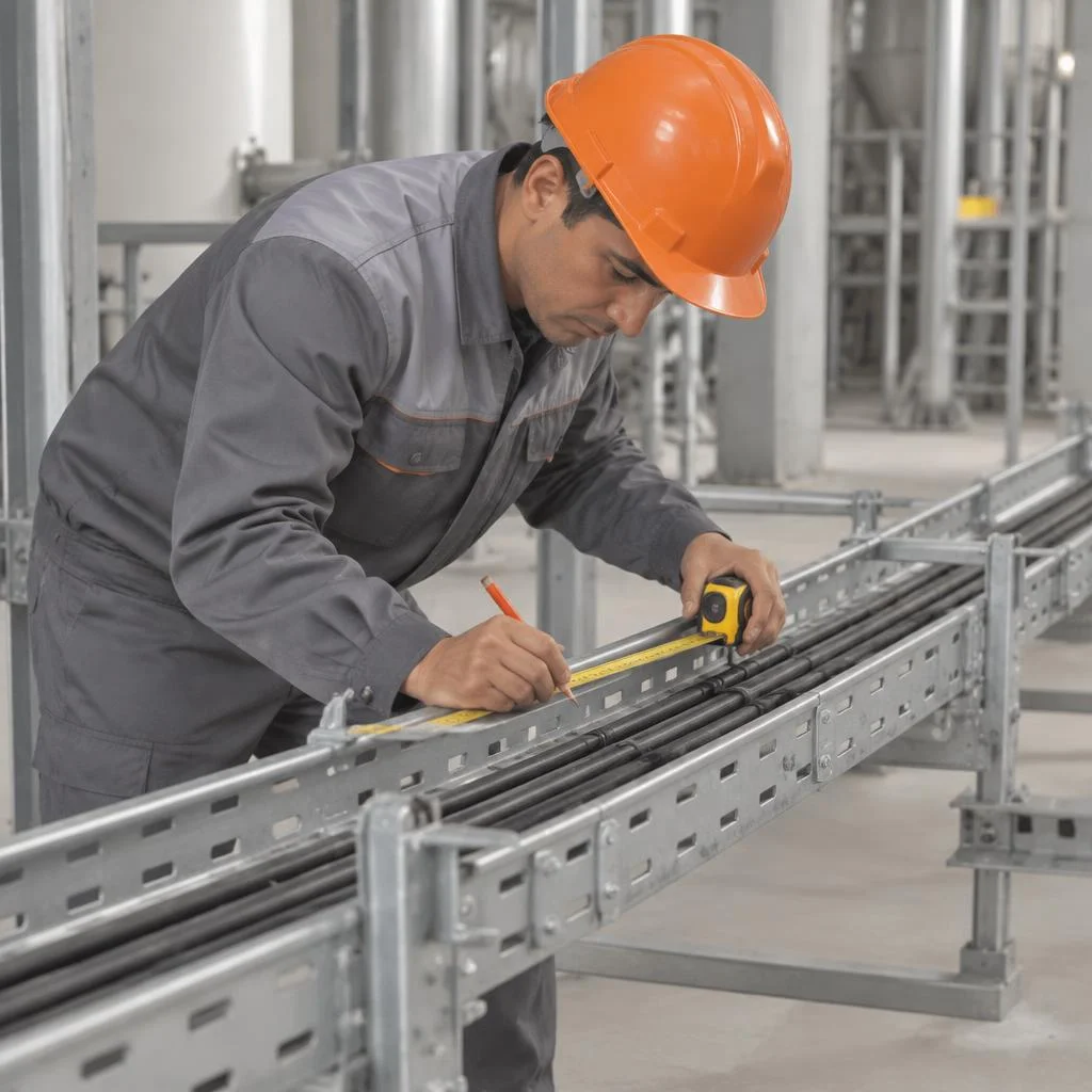
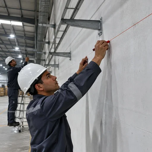
We start with route marking: we mark the axis of the line, the turning points and the locations for supports, taking into account the ceiling height and the position of the beams. At industrial facilities in Tashkent, the axis is set with a laser level at a height of at least 2.5 m, bypassing ventilation shafts, air ducts and other cable routes — the deviation of elevations along the length of the line does not exceed 5 mm per 10 m. In warehouses with corrugated sheeting, the marking is transferred to the lower flange of the corrugation, while on a monolithic slab the points are marked along the axial lines of the beams. Cable laying in trays begins precisely with this marking: until the axis is fixed, the installers do not drill a single hole. Route marking is carried out by Eco-Service, and at this stage we record each support with a marker and a number in the log. At facilities with corrugated sheeting, fastening into the upper flange sharply reduces the load-bearing capacity of the suspension — that is why we always mark along the lower flange, even if it takes longer.
Load calculation on the cable tray and support spacing
We calculate the load on the cable tray as the sum of the weight of the cable per metre plus the dead weight of the section, and from this figure we determine the spacing of brackets and cantilevers. For a power cable with a cross-section of 4×35 mm², the weight reaches 1.8 kg per metre; for control lines 10×1.5 mm² — about 0.4 kg; to this is added the mass of the tray (perforated — 2.5-3 kg/m, ladder — up to 5 kg/m) and a margin for fasteners. For such a route we set the spacing of the cantilever support at 1.5-2 m; for heavy ladder systems with 4×120 mm² cable — no more than 1.2 m. In Eco-Service, the load calculation on the cable tray is carried out with a factor of 1.3 for future additional tightening. If the project provides for line expansion, the support spacing is laid out for it in advance — otherwise, in six months the route will have to be re-fastened.
Tray fastening plan: what it records
- Type of support for the base: for concrete — a wedge anchor, for corrugated sheeting — a self-tapping screw for metal with a washer, for an I-beam — a clamp or welded bracket.
- Spacing and reach: the distance between supports along the entire length of the route and the cantilever offset from the wall, so that the tray does not rest against utilities.
- Anchoring and fasteners: the grade of M8 or M10 stud, the embedment depth of the anchor, the tightening torque for each type of base.
- Points of passage through walls and slabs: the locations for installing sleeves, the diameter of the opening and the gap for fireproof sealing.
- Laying cables in trays: the sequence of installation by sections and the order of fixing with clips, so that the plan can be read by the installer without explanations.
Installation technology: fastening, assembling sections and routing turns
Installation proceeds from supports to sections: first the fastening to the base, then the assembly of the line, then the turns and branches. Let's go through each stage with reference to the types of supports and bases.
Installation of brackets, hangers and cantilever supports
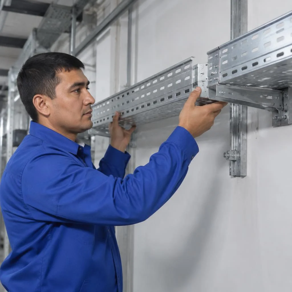
We install brackets for the tray, ceiling hangers and cantilever supports depending on the base: concrete, profiled sheeting or a metal structure. On a concrete slab we use an M8-M10 wedge anchor, into profiled sheeting we drive a screw with a washer into the lower flange of the corrugation, and to an I-beam and channel we attach a clamp or a weld-on bracket. A ceiling hanger on an M8 stud with an adjustment coupling sets the design offset of the tray from the ceiling, while a cantilever support works as an extension from the wall of 200-600 mm. We keep the support spacing according to the load calculation — the typical span between brackets is 1.5-2 metres for a medium tray. The laying of cable trays begins precisely at this stage, and on a concrete ceiling the hanger on a stud is adjusted in height after installation — this saves the day when the level difference of the slabs is more than a couple of centimetres and the route cannot be levelled by trimming the brackets. The installation of brackets for the tray and ceiling hangers at Eco-Service is carried out with a laser level to a single datum.
Fastening the tray to the profile and installing the crossbar
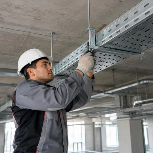
We fasten the tray to the profile through the standard holes of the section, and we install the crossbar where the load needs to be distributed onto two supports at once. For fastening the tray to the profile we use an M6 bolt with a nut and a flat washer, and we drill holes only in the wall of the section, not in the load-bearing rib — this preserves the rigidity of the profile. A crossbar made of 40×40 angle or C-profile is placed across two hangers and takes the weight of the route with the cable when the tray is wider than 300 mm or the support span is increased. On a narrow tray the crossbar allows the route to be extended from the wall by the required offset without additional brackets. One nuance: under the crossbar the fastening point is not clamped rigidly — a play is left for the thermal expansion of the metal, otherwise the section warps in winter. The installation of the crossbar for the tray and the fastening of the tray to the profile are carried out by Eco-Service specialists according to the fastening scheme from the project.
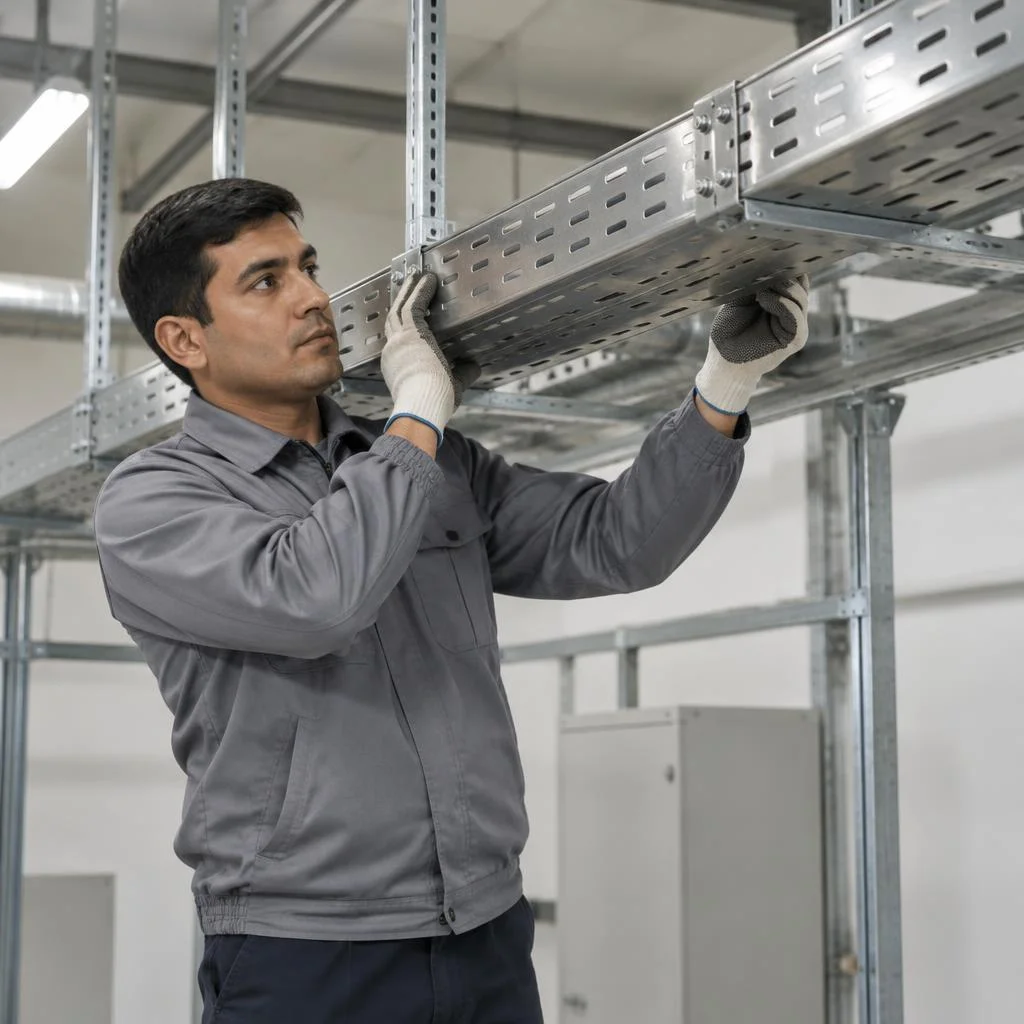
Connecting sections, turns, tees and adapters
- Connecting tray sections: the standard plate on M6 bolts pulls two sections together butt-joint, the gap between the ends is no more than 2 mm.
- Installing the turn element: a 90° or 45° angle is placed at the junction of straight runs, and a separate support goes under it.
- Installing the tray tee: a branch of the route in three directions, used when distributing to different panels or floors.
- Installing the tray adapter: a transition from a width of 200 to 300 mm and back, placed when the load on the line changes.
- Installing the end cap: closes the open end of the route on a dead-end section, protects the edge from injuries and dust.
Installation of trays on different bases: concrete, profiled sheeting, metal structures
| Base | Fastener | Feature |
|---|---|---|
| Concrete | wedge anchor | maximum load-bearing capacity |
| Profiled sheeting | screw with washer | fastening into the lower flange of the corrugation |
| Metal structure | clamp or welding | without drilling the load-bearing profile |
Into profiled sheeting you must not drive a screw into the thin lower flange without a washer — under the weight of the route the hole gets worn out, and the hanger starts to wobble within a month. The price of cable tray installation, which depends on the base and the type of supports, is calculated at Eco-Service after inspecting the ceiling: on profiled sheeting and a metal frame the fastening scheme differs from concrete, and this affects the scope of work. The laying of cable trays on metal structures is carried out without hot work where there are combustible materials nearby — a clamp is safer than welding here.
Laying cable in a tray: placement, pulling and fastening
After the route is assembled, work with the cable begins: laying on short sections, pulling on long ones, fastening with ties and marking the lines. Below is the sequence of operations that we have refined at sites in Tashkent.
Laying cable in a tray: sequence and fastening
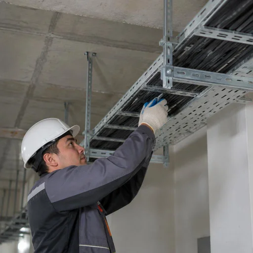
We lay cable in a tray in layers: power lines separately from low-current lines, with fastening by ties at equal intervals along the length of the route. First we lay out the cable along the section without tension, leaving slack for thermal elongation, then we cinch it with nylon ties at a spacing that we select according to the weight of the bundle and the cable cross-section. At bends and at entry points into the cabinet we install soft pads so that the insulation does not rub against the metal edge. Power and low-current cables in the same tray are routed along different sides of the section — this is cheaper than installing a separate route, and it eliminates interference on communication lines. During installation at Almaty sites, we label each bundle with tags on both sides — during subsequent maintenance this saves hours of searching for the required line.
Pulling cable along a tray on long routes
Pulling cable along a tray on long routes is performed with intermediate rollers and division into sections so as not to exceed the permissible pulling force. We place the drum at the start of the route, pull the cable with a winch or by hand through roller guides installed every 8-12 meters, and on turning elements we mount corner rollers. For large-cross-section copper lines the permissible force is limited — exceeding it leads to stretching of the conductor and an increase in resistance. If the cable is pulled in a single span through several turns, the insulation wears against the edge of the tray at the corners — rollers at the turns are cheaper than redoing the section. Before pulling, we check the cleanliness of the edges and the absence of burrs after cutting — on stainless steel and ladder trays this is especially critical.
Passage of cable through walls and floors
At points of passage through walls and floors we install a sleeve and seal the gap with a non-combustible compound — this is a fire safety requirement. The sleeve is selected with a margin in diameter: if the cable enters the wall with tension, during thermal expansion it pushes through the seal and the fire resistance of the assembly is lost. We drill the hole in concrete with a slope toward the outlet so that water does not flow inside, and on the outside we apply sealant around the perimeter. At industrial sites in Samarkand and Bukhara we additionally ground the metal sleeve if it passes through a reinforced frame. After sealing, the assembly is marked — during acceptance, the fire inspector checks precisely these points first.
Standards, grounding and typical installation errors
A cable tray route is part of an electrical installation, so installation follows the Electrical Installation Code (PUE), and grounding and fastening spacing are checked when the facility is handed over. Let's break down the regulatory framework and the errors that surface during acceptance.
PUE requirements for cable tray routes
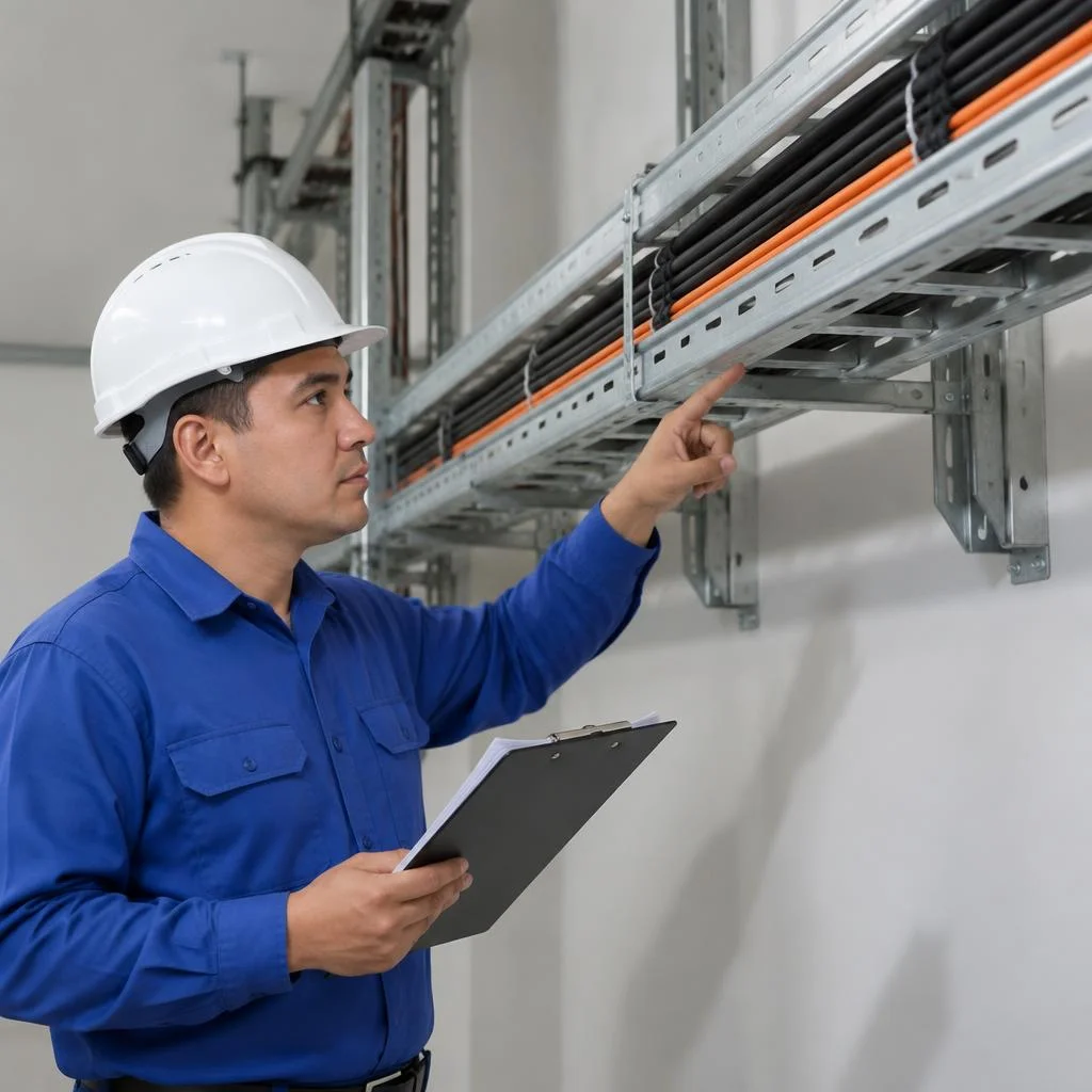
Laying cable trays in accordance with the PUE is subject to requirements for route fill, distances between power and low-current lines, fastening spacing, and mandatory grounding of the metal duct. Fill is calculated by the total cross-sectional area of all cables, not by their count: for power lines the norm is no more than 40% of the usable tray cross-section, for low-current lines up to 50% is allowed. Fastening spacing depends on the tray type and the weight of the route: wire mesh trays are fastened every 1-1.5 meters, perforated and ladder trays — every 1.5-2 meters, and at bends and near tees supports are installed additionally. The distance between power and low-current lines in the same tray is at least 100 mm or a dividing partition. A tray packed to the brim fails the heat check even with a formally permissible number of lines, so fill is verified by calculation before installation, not after the cable is laid.
Tray grounding: why and how
We ground the metal tray along the entire length of the route: sections are connected with jumpers, and the line itself is connected to the building's grounding loop. For continuity of the circuit, a section connector with a jumper of at least 6 mm² cross-section is installed at every joint, and the route is welded or bolted to the grounding main at two points — at the beginning and at the end of the line. Paint and zinc coating at the section joint do not provide reliable contact: the jumper is installed over the coating with cleaning down to bare metal, otherwise the route is formally grounded but in fact is not. Through Eco-Service, tray grounding is performed with verification of transition resistance — the norm for such a circuit is no higher than 0.1 Ohm, and this figure is recorded in the acceptance report. On long lines over 50 meters, intermediate connection points are added, because resistance increases with every joint.
Typical errors in tray installation and their consequences
- Excessive support spacing: saving on brackets causes the route to sag under the weight of the cable and deformation of sections at the joints.
- Missing grounding jumpers: the tray looks grounded, but the transition resistance at the joints exceeds the norm several times over.
- Fastening to thin profiled sheeting without a washer: the hanger pushes through the metal, and the route sags along with the roof sheet.
- Power cables right next to low-current ones: interference distorts the signal, and when the power line heats up, the low-current insulation suffers.
- Installing cable trays without cross-section reserve: after the cable is pulled tight, the route fails the fill check, and the line has to be re-laid.
Conclusion
We have gathered the key points that determine the outcome for a cable tray route: from choosing the tray type to sealing penetrations. Below are five conclusions worth keeping at hand when accepting work and planning the next facility.
Key conclusions
- Tray type: chosen by load and operating environment, not by the price of a section — a cheap option in a workshop with an aggressive environment ends up costing more than a replacement.
- Three stages before installation: route marking, load calculation and fastening scheme are performed separately and before the first bracket.
- Support spacing and grounding: verified by calculation and PUE requirements, not by the fact that the route sags on the installed section.
- Laying and pulling: these are different operations with different tools — laying is done in sections, pulling requires a winch and rollers on long runs.
- Penetrations through walls and floors: sealed with a sleeve and a non-combustible compound, otherwise the fire resistance of the barrier is lost and a bridge for moisture appears.