








Why a house needs grounding and how it works
Grounding is not an optional extra, but a mandatory condition for the safe operation of an electrical installation. We break down how the ground loop diverts leakage current, which resistance standards apply, and why gas equipment cannot do without it.
What a ground loop is and how it protects
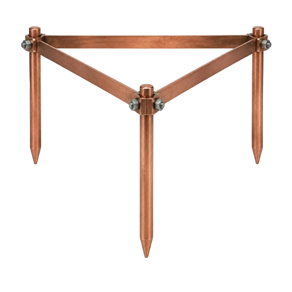
A ground loop is a system of buried electrodes connected by a conductor that diverts leakage current into the soil and prevents the potential on the appliance's casing from reaching a dangerous value. The electrodes are driven to a depth of 2.5-3 m into the frost zone or below, connected with a 40×4 mm strip, and run to the main panel with a separate core. When a phase breaks through to the metal casing of a washing machine or water heater, the current flows through the grounding conductor into the ground, not through a person. In combination with a circuit breaker, this works as a single mechanism: with a 30 mA leakage, the RCD opens the circuit in 0.3 seconds, but only if there is a path for the leakage current. Without a ground loop, the RCD may not trip when touching an energized casing — the protection only works in the pairing of "grounding + circuit breaker." People often search for "organizing grounding in a private house" — and land on this page. In my view, this is exactly why skimping on the ground loop to save on a single circuit breaker is the most expensive mistake in a private house.
Resistance standards: 30 Ohms and 10 Ohms
- 380 V, house service entrance: spreading resistance — up to 30 Ohms, this is the basic standard for electrical installations with a solidly grounded neutral.
- Gas equipment: up to 10 Ohms, a separate requirement for boilers and stoves connected to mains gas.
- Re-grounding: up to 30 Ohms at the service entrance of an overhead line, if several buildings are powered from it.
- Seasonal correction: in summer, dry soil gives resistance 1.5-2 times higher than in spring, so measurements are taken during the most unfavorable period.
- What affects it: soil resistivity, electrode length, the distance between them, and the burial depth — loam retains moisture better than sand.
Why grounding is mandatory for a gas boiler in Tashkent
A gas boiler requires a separate ground loop with a resistance of up to 10 Ohms — without it, the gas service will not sign the documents, and the boiler's automation may operate incorrectly. In Tashkent houses with mains gas, an inspector checks the measurement report before starting up the equipment, and installing the ground loop becomes part of the acceptance process, not an option. A separate ground loop for the boiler must not be combined with the "neutral" conductor in the panel — this is a common mistake that causes the protection to stop working: if the neutral breaks, the boiler's casing ends up under phase voltage, and the circuit breaker does not see it. Moreover, for gas equipment, not only the resistance value is critical, but also the continuity of the circuit from the electrode to the terminal on the casing. Check the integrity of the conductor with a multimeter after every repair in the boiler room — a loose contact in the terminal block nullifies the entire ground loop.
How Tashkent's soils influence the choice of solution
The soils of Tashkent and its suburbs are loess-like loams and sandy layers that dry out to a depth of up to 2 m in summer and raise the spreading resistance by one and a half to two times. In the center, in the Yunusabad and Mirzo-Ulugbek districts, dense clay often lies beneath the top layer — it retains moisture more consistently, and the classic triangle of three rods works predictably there. In Chilanzar and Sergeli, sandy lenses are found: a single electrode in such soil gives a weak result, so you have to increase the number of rods or drive them to a greater depth. The resistivity of loam ranges from 40-150 Ohm·m depending on moisture, and you cannot judge the entire plot from a single sample — we measure at three or four points around the perimeter. Clients often search for "grounding busbar installation price" — that is how the query lands on this page, although what is meant is the full scope of work. If the plot is difficult, it is cheaper to build in a reserve of electrodes right away than to dig up the yard a season later and extend the ground loop, which is why ground loop installation is planned before finishing work begins.
Grounding loop diagrams: what to choose for a private house
The loop diagram is selected based on the soil, the plot area, and the type of facility. Below is a comparison of the three main options that we install in Tashkent, with the parameters and features of each.
Classic 3×3 m triangle for a private house
Eco-Service installs a classic triangle with 3×3 m sides made of 50×50×5 mm angle steel, buried to 2.5-3 m — this is the basic diagram for a house with clay soil. The three vertical electrodes are connected to each other by a 40×4 mm steel strip in a trench 0.5 m deep. The distance between the rods is maintained at no less than their length: if the electrodes are brought closer than 1.5 m, the spreading zones overlap, and the resistance increases instead of decreasing. A grounding loop for a private house on such soil delivers stable performance without special machinery. The triangle occupies a 3×3 m corner of the plot and does not interfere with plantings or a pathway. We begin the installation of grounding in a private house by checking the soil composition with a hand auger to the freezing depth — on sandy loam the diagram is reinforced with a fourth electrode, otherwise the resistance standard is not met during the dry season.
Linear diagram and indoor loop
We use the linear diagram on narrow plots and indoors — the electrodes are arranged in a row and connected by a 40×4 mm strip. Along a fence 2-3 m wide, a triangle physically cannot be laid out, while a line of three or four rods with a 3 m spacing fits freely. Inside a building, the indoor grounding loop is installed in the basement or a technical pit: the same angle steel is driven along the walls, and the bonding runs as a strip at a height of 0.4-0.5 m from the floor. When organizing grounding in a private house with finished interiors, it is important to agree in advance on the entry points for the grounding conductor to the panel — otherwise you will have to chase the walls after renovation. In our projects, we route the conductor through a sleeve in the foundation before the floors are poured.
Comparison of grounding diagrams for a house
| Diagram | For which facility | Electrode depth | Installation feature |
|---|---|---|---|
| Triangle 3×3 m | Private house, clay soil | 2.5-3 m | A 0.5 m trench is required |
| Linear | Narrow plot, indoor | 2.5-3 m | Electrodes in a row |
| Modular rod | Rocky soil, dense development | 6-30 m | Driving of rods |
| Deep grounding | Difficult soil, industrial facility | up to 30 m | Special machinery required |
Installing grounding in a private house on rocky soil using the classic diagram often does not provide the required resistance — in such geology we recommend the modular option right away, so as not to visit the site a second time. Design begins with calculating the number of electrodes for the specific soil, not with a ready-made template. The final cost depends on the diagram and the immersion depth: the modular option is more expensive than the classic one, but on stone there is no alternative.
Grounding installation: work stages from marking to connection
Grounding installation is a sequence of four stages, each of which affects the final resistance. Let's break down exactly what we do on site: from marking and earthworks to connection to the main panel.
Marking the loop and earthworks
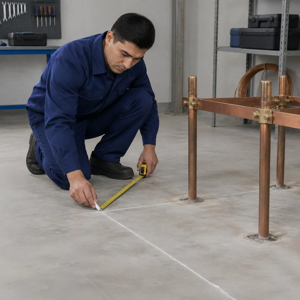
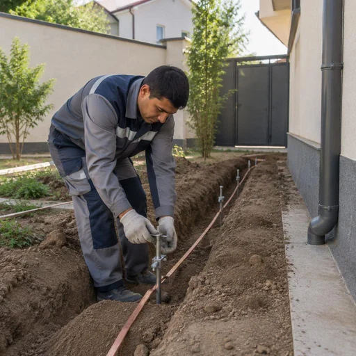
We start by marking the loop according to the plan and dig a trench 0.5 m deep — at this stage the geometry of the future ground electrode is determined. We install the outdoor loop as a 3×3 m triangle for a private house or as a linear layout along the wall for constrained plots, and the price depends on the length of the trench and the number of driving points. In the dense built-up areas of Tashkent (Mirzo-Ulugbek, Yashnabad districts), we first check the route against the utility plan: the gas pipeline, water supply and power cable lie at a depth of 0.8 m or more. Marking should be done with a margin from the foundation and utilities — a damaged cable or pipe during earthworks costs more than a loop shifted by a meter. We perform the marking and earthworks on site.
Installation of vertical ground electrodes and welding of the loop
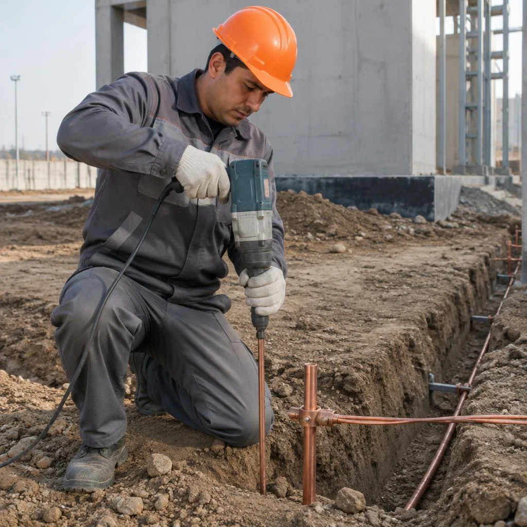
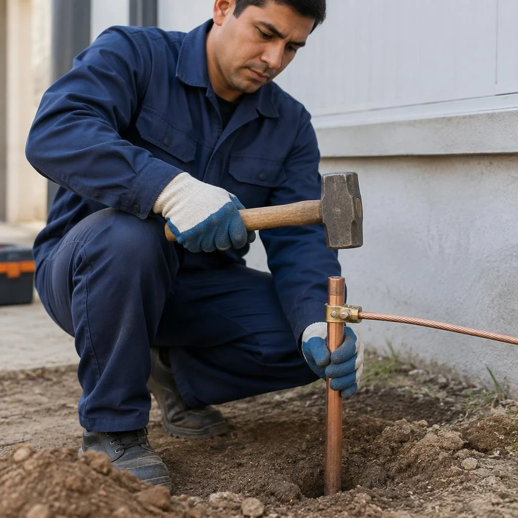
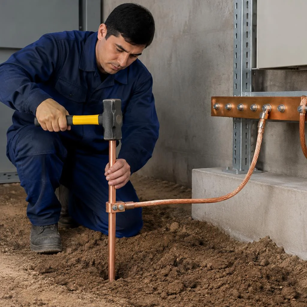
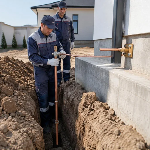
- Driving the electrodes: we drive 50×50×5 mm angle steel to a depth of 2.5-3 m with a vibratory hammer or a manual tamper, leaving 15-20 cm above the bottom of the trench.
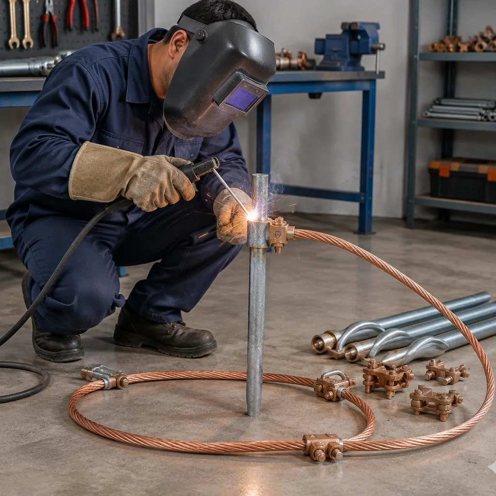
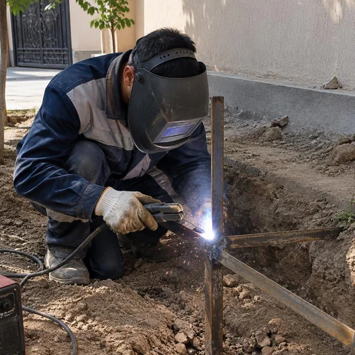
- Welding the loop: we connect the vertical ground electrodes with 40×4 mm strip into a single loop, with a weld of at least two adjoining sides for reliable contact.
- Treating the weld: we clean off the scale and coat the welded joint with an anti-corrosion compound — without this, after a few seasons the contact loses conductivity.
- Checking the geometry: we monitor the distance between the electrodes and the driving depth so that resistance is distributed evenly across the entire loop.
- Control continuity check: we check the continuity of the circuit at all welded points before backfilling the trench.
Laying the grounding conductor and connecting to the panel
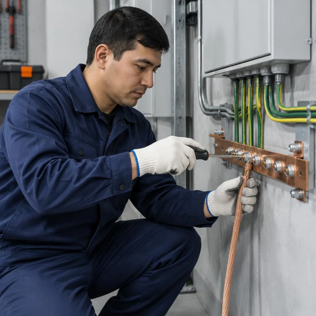
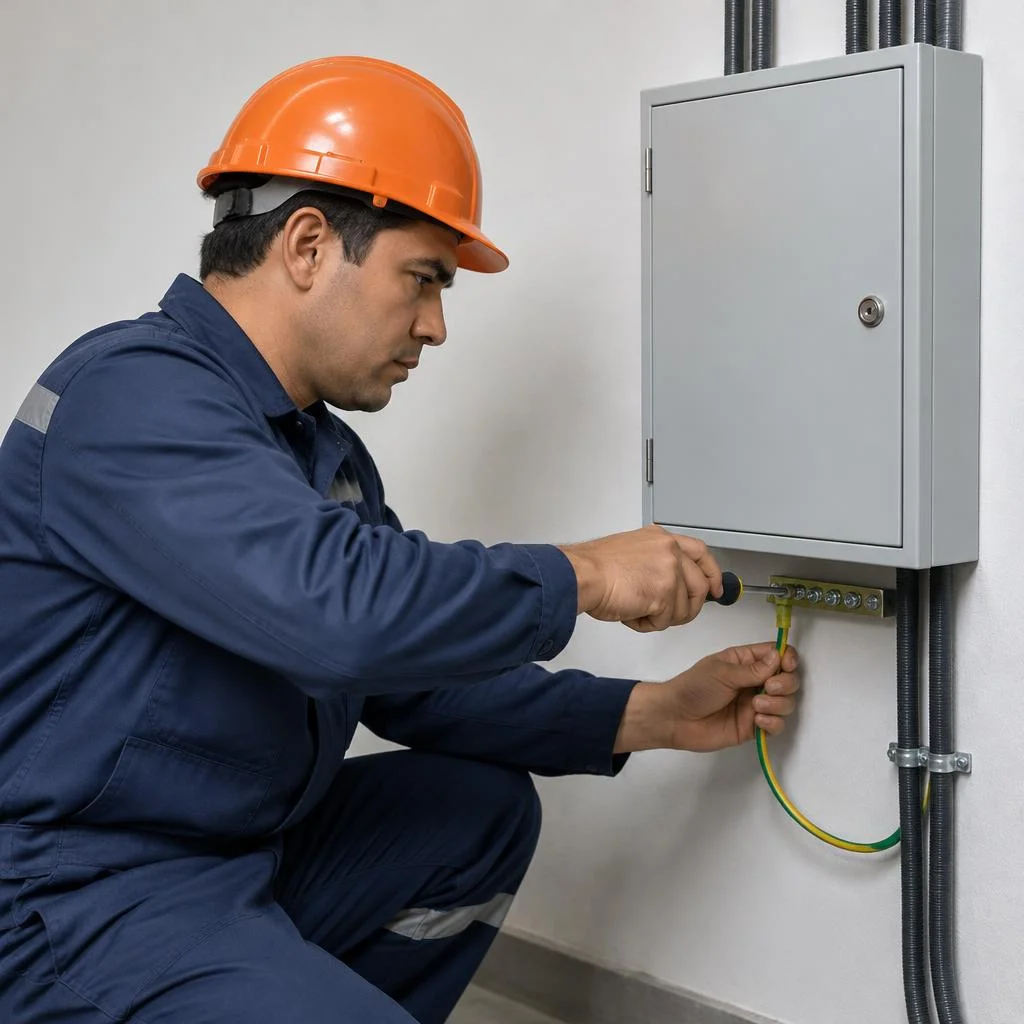
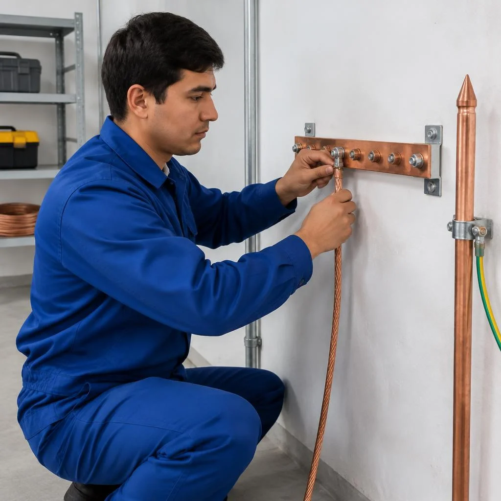
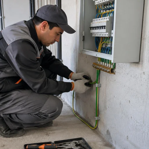
We lay the grounding conductor from the loop to the main panel and connect it to the grounding busbar with a bolted connection. The price of the strip per meter depends on the cross-section and the laying method, and the cost of the busbar depends on the number of connected lines in the distribution device. We run the conductor as 40×4 mm strip or copper cable with a cross-section of at least 10 mm², fasten it to the wall with dowel clamps at 0.5 m intervals, and bring it into the panel through a sleeve. The conductor must not be run through places where mechanical damage is possible — where it crosses utilities, we protect it with a sleeve. We perform the connection to the main panel and the laying of the conductor.
Installation of protective grounding on site
We install protective grounding for all electrical equipment on site — from socket groups to machines and panels, combining them into a common system. The installation covers panel enclosures, metal cable sheaths, machine frames and household appliance housings; the cost of grounding in a private house depends on the number of connected groups, and the indoor loop is assembled along a closed perimeter inside the workshop or basement. At an industrial facility, protective grounding is designed together with the potential equalization system — otherwise the potential difference between enclosures remains dangerous. In the private sector, metal staircases, canopies and greenhouse frames are additionally connected to the loop if they fall within the touch zone. Protective grounding on site is installed by Eco-Service.
What to do after installing the loop
Clients often phrase the request like this: how much does a loop cost — and that is exactly what we calculate after visiting the site. The final sum is made up of the volume of earthworks, the number of ground electrodes and the length of the conductor to the panel, so it cannot be quoted over the phone without an inspection. We complete the work with a control measurement of the current spreading resistance and a check of the phase-neutral circuit before energizing. Without these two measurements, the loop is considered not installed: even correctly assembled geometry can give resistance above the norm due to the soil composition. The cost is calculated after visiting the site — based on the number of driving points and the length of the route, and we fix the final estimate before starting work.
Modular and deep grounding for difficult soils
On rocky and dense soil, the classic triangle does not provide the required resistance — we break down the modular and deep solutions that we use in such conditions.
Modular rod grounding: composition and installation
- Copper-bonded rod: a steel core with a 250 µm copper coating provides conductivity and protects against corrosion for decades.
- Coupling: a threaded or crimp connector extends the rod to the design depth without loss of contact.
- Tip: a pointed element on the lower rod for passing through dense layers and inclusions.
- Driving head: the attachment absorbs hammer blows and prevents the thread from being crushed during driving.
- Depth: 6-30 m depending on the soil — the lower the water-bearing layer, the fewer rods are needed.
Deep grounding and rocky soil
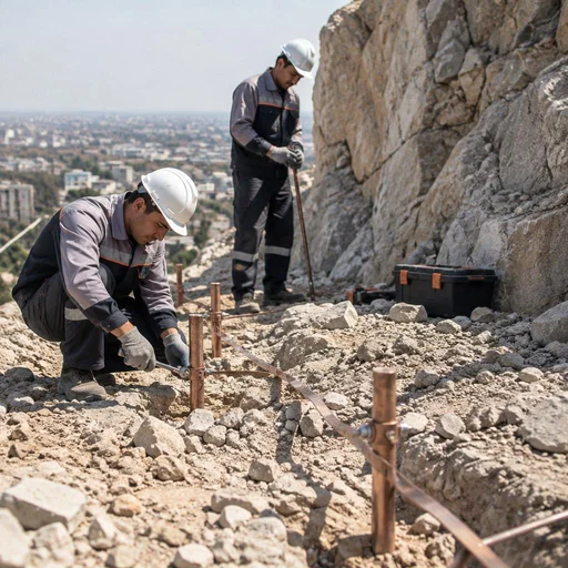
For rocky soil, we use deep grounding with electrodes buried to 30 m — this is the only way to achieve stable resistance. The rocky formations of the Tashkent region — loess-like loams with inclusions and limestone outcrops — do not allow an ordinary rod to be driven to the required depth, so we use a deep ground electrode installation with pre-drilling. In dense layers, we go deeper with a composite copper-bonded electrode and graphite backfill around the shaft — it reduces transition resistance by 1.5-2 times. Installing grounding in rocky soil requires a test driving to 2-3 m: based on it, we determine whether to drill a borehole or work with a vibratory hammer. The standard is achieved through depth, not area — this is important when the plot for the grounding loop of a private house is limited.
Grounding for an industrial facility
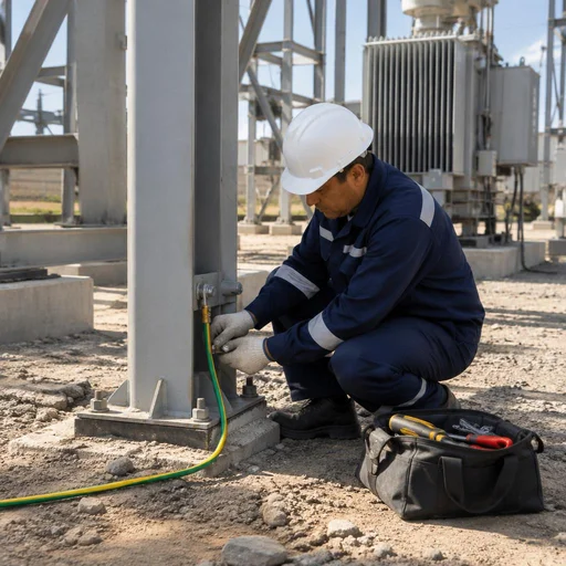
For an industrial facility, we design a loop taking into account the power of the equipment and resistance requirements, including the installation of grounding devices along the entire perimeter. We carry out such grounding installation according to a project with provision for expansion. Grounding for an industrial facility is done with modular rods at the corners of the building and along cable routes, welding the strips into a single network. We calculate the resistance separately for each group of consumers: machines, panels, metal structures. At facilities with several inputs, the industrial network and the grounding loop for the house are designed on the same principle — a single potential equalization point. At Eco-Service, such loops are designed with provision for production expansion: the laid strip allows adding rods without redoing the entire system.
What influences the choice of solution
| Soil and conditions | Solution | Depth |
|---|---|---|
| Loam, space available | Classic triangle | 2.5-3 m |
| Dense soil, little space | Modular rod | 6-12 m |
| Rocky soil | Deep with drilling | up to 30 m |
| Industrial site | Modular along the perimeter | 9-15 m |
How soil changes the estimate and timelines
The type of soil determines not only the scheme but also the scope of work: on loam, three rods are enough, while on a rocky base the count is in meters of drilling. The grounding loop price depends on the number of rods and the volume of earthworks, so the total is calculated after a test driving. Customers often ask about the final cost — it is influenced specifically by the composition of the rock, not the area of the plot. When clients search for grounding strip installation, they usually mean connecting the rods into a single network along the perimeter, and here not only the footage but also the welding method matters. A separate line in the estimate is the calculation after a site visit, because the sum is made up of the depth, the number of points and the difficulty of access for equipment. The grounding loop of a private house on a rocky base sometimes costs more than a typical project, but it serves for decades without repair.
Lightning protection in conjunction with the grounding loop
Lightning protection without grounding is useless: the discharge needs somewhere to go. We explain how we combine the air terminal, down conductor and loop into a single complex for a home and an industrial facility.
Air terminal and down conductor
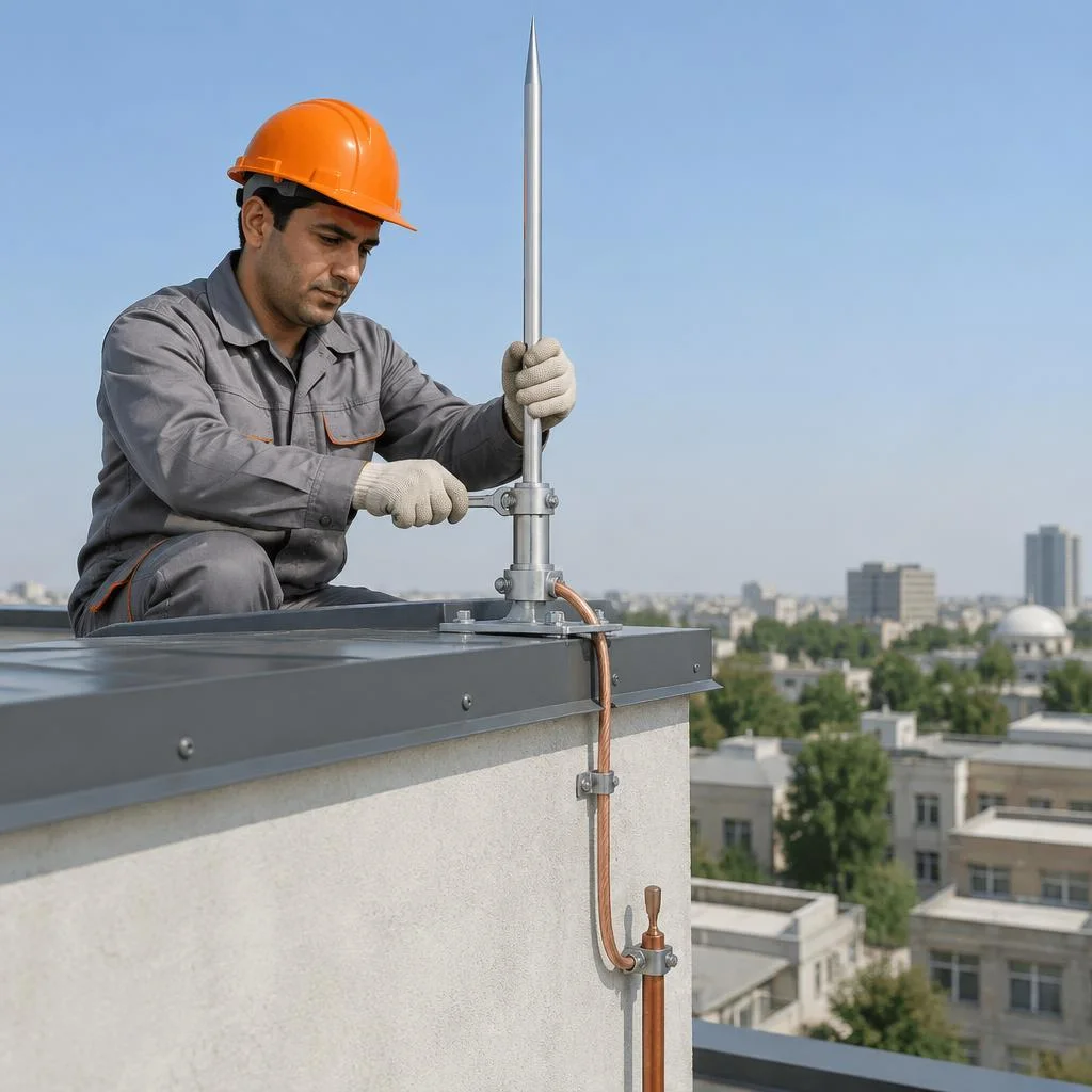
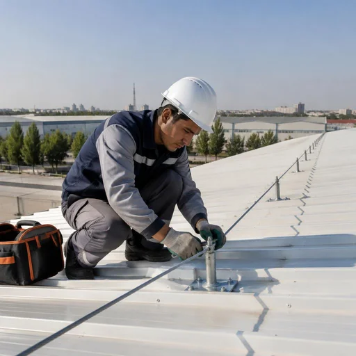
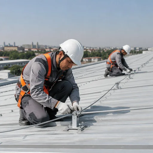
We install the air terminal on the roof and route the down conductor to the grounding loop along the shortest path. When arranging the loop, grounding in a private house and lightning protection are designed as a single system: a galvanized steel rod 16 mm in diameter or a copper pin is fixed on the ridge or the highest point, and the down conductor made of 25×4 mm strip or wire with a cross-section of at least 16 mm² runs down the wall. Every turn of the route increases inductive reactance — with a 100 kA discharge, an extra 90° bend adds tens of kilovolts of drop, so we run the descent as straight as possible, and connect the down conductor to the loop via welding or a bolted connection with anti-corrosion treatment. The down conductor must not be fastened to combustible roof elements — during a discharge it heats up, and this creates a fire risk.
Lightning protection mesh for roofing
We install the lightning protection mesh on flat and pitched roofs as an alternative to a single air terminal — it distributes the discharge over the entire area. A 5×5 m or 10×10 m cell is assembled from 25×4 mm strip or 8 mm round steel, laid over the roofing with a fastening pitch of 1 m and connected to the down conductors at the corners of the building. Through Eco-Service you can order the installation of protective grounding together with the mesh: the receiving part, descents and the grounding loop in a private house are combined into a single project. The mesh is more effective on roofs of complex shape: a single rod protects only a limited zone, while the mesh covers the entire slope.
When a modular ground electrode is needed for lightning protection
Installing modular grounding solves the problem when low impedance is needed for the air terminal, and the soil is dense or dry. Clients often find us via the query modular grounding installation — and land on this page. The final cost is made up of the driving depth of the pins, the number of sections and the type of soil: on the loam of Tashkent, 2-3 modules of 1.5 m each are enough, on pebble or rocky ground the number of sections rises to 6-8, and sometimes bentonite backfill is added to reduce resistance. The modular pin system is assembled by pressing or vibratory driving — without digging a 3-meter trench, which is critical on plots with tiles or asphalt already laid. We always connect the air terminal, down conductor and modular ground electrode into a single circuit: a break at any node devalues the entire protection, so every connection is checked for transition resistance.
Resistance measurement and protocol: how the result is verified
An installed loop without measurements is unfinished work: resistance figures confirm that the earthing installation has been carried out to standard. We break down the instruments, the procedure for testing the phase-neutral circuit, and the contents of the protocol.
How earthing resistance is measured
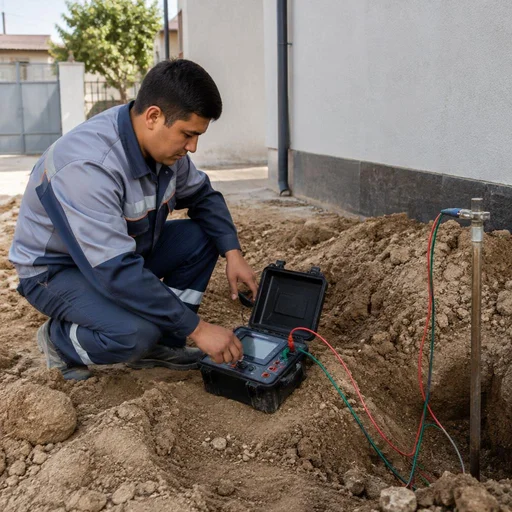
- Instruments: M416 (analogue), IS-20 and MRU-200 (digital) — the latter save the result straight to memory.
- Setup: three-wire — the potential probe at 20 m, the current probe at 40 m from the loop in a straight line.
- Method: ammeter-voltmeter; if the soil resistance is above 100 Ohm·m, we add a fourth wire.
- Season: the dry period, when humidity is at its lowest and resistance at its highest.
- Standard: for a house earthing loop — no higher than 30 Ohm, for a gas boiler — 10 Ohm.
Testing the phase-neutral circuit
Testing the phase-neutral circuit confirms that the circuit breaker will trip in the event of a short circuit to the enclosure — whether the line disconnects in fractions of a second or remains live depends on this. The specialist measures the total impedance of the loop formed by the phase conductor and the neutral protective conductor using an MRU-200 in Zloop mode, calculates the expected single-phase short-circuit current and checks it against the breaker's characteristic on the time-current curve. For a socket group with a C16 breaker, the calculated short-circuit current must exceed 160 A — then tripping is guaranteed in the instantaneous release zone. Even with normal loop resistance, the phase-neutral circuit may fail to ensure disconnection due to excessive loop impedance — testing identifies this before the facility is commissioned. Clients often look for this service using a query about measurement — and land on our page, even though it concerns a different stage of the work.
The measurement protocol and what it records
The measurement protocol is drawn up stating the loop resistance, the measurement method and the instrument — the document is accepted by gas and supervisory services when connecting a boiler and handing over a facility. The form records the earthing electrode's nameplate data, the weather conditions at the time of measurement, the soil temperature and humidity, the layout of the electrodes, the values for each measurement and a conclusion on compliance with the standard. For gas equipment, the protocol is supplemented with a measurement of the re-earthing resistance of the neutral conductor. It makes sense to draw up the document immediately after installation: a repeat visit by the crew for measurements a season later will cost more than the initial paperwork on the day the work is handed over. Through Eco-Service, the protocol is prepared on the same day the crew completes the assembly of the earthing devices at the facility. The form records the type of facility on a separate line — a house earthing loop, an industrial substation or a power line pylon — as this determines the set of standard values.
What to do if it deviates from the standard
- Measure the soil: if the resistance is above 30 Ohm, the humidity and composition of the soil at the depth of the rod are checked.
- Add electrodes: the modular rod earthing device is extended by 1-2 sections of 1.5 m each.
- Reinforce the assembly: oxidised connections are re-welded and the conductor is replaced with a 16 mm² cross-section.
- Recalculate the layout: with rocky soil, they switch to deep earthing with conductive backfill.
- Repeat the measurement: a control measurement after the modification records the result and goes into a new protocol.
When the standard is not achieved, it is important to understand the contribution of each electrode: an earthing loop device with an even spacing of rods sags at the edges rather than in the centre — that is where a section is added. Installing an earthing loop in the clay soil of Tashkent provides a margin on resistance, while in sandy soil it requires extending the rods, so the modification is planned before the repeat measurement.
Warranty, timelines and organization of work
We explain how the work is organized: timelines, warranty and what is included in the contract. Below are the terms that apply at sites in Tashkent and across the country.
2-year warranty on the installed loop
Eco-Service provides a 2-year warranty on the installed grounding loop — it covers welded joints, fastenings and resistance stability. The contractor records in the act every welding point, the electrode grade and the parameters of the rods, and confirms the result with a measurement protocol using MRU-200 or IS-20 instruments. Over the two-year period, an engineer visits for a control measurement of the current-spreading resistance: if the value has risen above the design one, the joints are re-welded at the contractor's expense. Clients often search for "installation of an external grounding loop" — and land on this page, although the final cost is calculated only after a visit to the site. The warranty remains valid provided that the customer does not carry out earthworks in the loop area without approval — mechanical damage to the electrodes is not a warranty case. Before starting any work on the plot, check against the routing diagram from the project: digging to a depth of more than half a meter within the radius of the loop is most often what causes a break in the connection between the electrodes.
Installation timelines and work procedure
- Request: the customer submits an inquiry by phone, in Telegram or through the website with the site address and the type of building.
- Inspection: an engineer visits the plot, assesses the soil, the length of the route and the entry point into the panel.
- Contract: the parties fix the loop diagram, the scope of work, the timeline and the warranty obligations.
- Grounding installation: the crew performs marking, digging, installation of the rods, welding and connection to the main panel.
- Protocol: after the control measurement, the customer receives a completed resistance measurement protocol.
Own service center in Tashkent
Eco-Service has its own service center in Tashkent — the customer can come in person, discuss the project and conclude a contract for grounding installation. The reception is handled by engineers who themselves visit sites: they go over the plot plan, show samples of rods and modular ground electrodes, and explain the difference between a triangle and a linear layout for specific soil. An in-person reception allows the loop diagram to be agreed immediately based on the plot plan — this is faster than correspondence and reduces the risk of errors in marking. Clients search for "installation of grounding devices" — and the engineer at the meeting immediately shows how such a loop differs from a simplified layout. Bring a cadastral plan or at least a sketch with the boundaries of the building and the electricity entry point: with them, the engineer will calculate the length of the conductor and the number of electrodes right at the meeting.
Conclusion
The review is complete — below are five points worth keeping in mind before starting work at a site.
Main takeaways
- Layout for the soil: a 3×3 m triangle works on clay and loam, while modular-rod or deep grounding is for rocky ground and dense strata.
- Resistance standard: up to 30 Ohms for electrical installations and up to 10 Ohms for gas equipment; the measurement is taken with an instrument in the dry season, when the soil gives its maximum value.
- Six installation stages: marking, earthworks, driving in the electrodes, welding the loop, laying the conductor, connection to the panel.
- Lightning protection without a loop is useless: the down conductor and the mesh are connected to the common grounding system, otherwise the discharge goes into the roof.
- The measurement protocol is mandatory: it is precisely this that gas and supervisory services accept when the site is commissioned.